Function
Baseline Offset is a simple mapping technique that allows you to add coordinate points into your drawing manually. Measurement data is typically gathered with tape measure, measuring wheel or handheld laser distance meter. Multiple baselines can be inserted into one diagram.
Procedure
The term baseline offset means that measurements used to determine the map coordinates (offsets) are based at 90 degrees from a fixed straight line (baseline).
After selecting the Baseline Offset command, you will be prompted to select your baseline origin point followed by an end point. This defines direction and orientation of a fixed straight baseline from which your 90° offset measurements will be measured from. Your baseline may represent a wall, fence line, sidewalk, etc. at your scene and should be oriented in either a vertical N-S or horizontal E-W direction for simplicity.
The first click (1) sets the 0,0 coordinate which is your Origin Point. The second is end point (2) used to define the direction and orientation of the baseline axis.

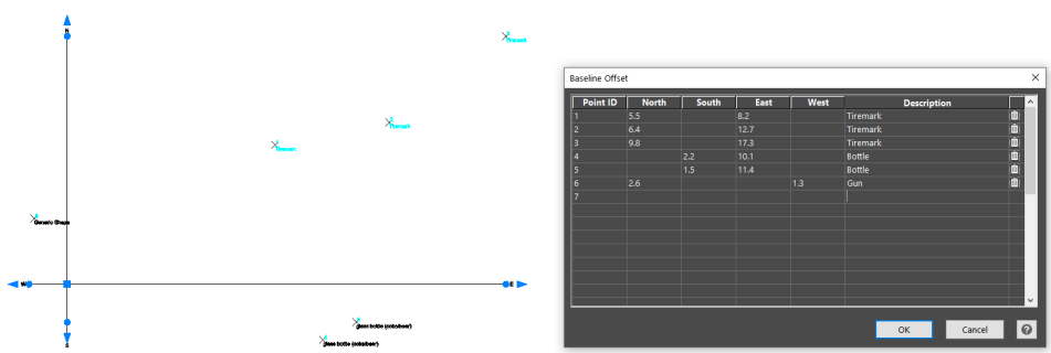
Once you have left clicked both points on screen you will see an XY axis with N,S,E,W quadrants labeled and a Baseline Offset dialog box for data entry.
Enter the measurement data in the dialog table. Use the Tab key to skip to next box as you enter values. Coordinate points and descriptions will appear in the diagram as they’re entered.
The distances will be the same as your selected drawing units, in feet or meters. However, if the drawing units are feet and entered as 8’ 2” then it will automatically convert this to decimal feet.
Edit values in the table and the points will automatically update when changes are made. If you need to delete the row click on the garbage can icon at the end of the row, a message will appear, “Are you sure you want to delete the data in this row? Yes or No” If Yes, then the point will be deleted.
Press OK when you are finished or to pause your work. To reopen an existing baseline to resume work, double click on either one of the axis lines. The data entry dialog table will display allowing you to resume your data entry.
Once your data entry is completed press ok. You can create an Evidence Log to accompany your diagram with a list of your points. This command is found under the ribbon menu under the Data Tab. Any changes will appear with red flag and when selected will list the revision made. Note: if Evidence Log does not seem to appear, check to see if it is minimized near bottom of your screen and maximize to view.
The baseline offset tool can be modified from the properties panel or adjusted with the grips.
Note: If a user moves or rotates the baseline, a warning will appear warning the user that all points will be updated – Continue? Yes or No. The points are tied to the baseline and must update accordingly. If the user says no to the warning or to any of the point protection points, the base line tool will revert to where it was before the change and all points will remain unchanged.