Function
This routine will reconstruct and draw a trajectory line and/or error cone indicating the possible angle of the bullet path, from measured data points connected by a line or from scanned rods.
Procedure
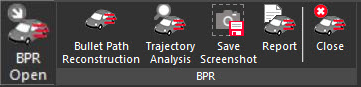
The BPR Open button on the Analysis Ribbon in the Default workspace will display a dedicated ribbon with features specific to the Bullet Path Reconstruction (BPR) workflow.
The Bullet Path Reconstruction button is the first step in the workflow. The dialog will appear allowing a user to create trajectory cones from the scene data.
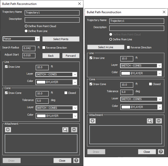
A unique name can be entered for each trajectory. The default name is Trajectory1 and this name will increment to Trajectory2, Trajectory3, etc. A description can also be entered for each trajectory.
Define the trajectory from either the Point Cloud data or from a Line. The point cloud option is disabled if there is no point cloud in the drawing.
Choose the reconstruction method and Select Points/Select a Line.
Line: Use this option to pick a single line in the drawing. The line will become the center line of the trajectory.
Fence: Use this to create a fence around the scanned trajectory rod. This is the default method. A best-fit line algorithm will be applied to all points falling within the fence. Note that the fence is not bounded by the search radius, so you need to make sure that there are no unrelated points behind the rod (such as a wall or another rod).
Fit Points: Use this to pick 2 points from the point cloud that are on a scanned trajectory rod. A best-fit line algorithm will be applied to all points that are within the "Search Radius" distance from the line connecting these two selected points, which if set appropriately will bound all of the scanned points along the rod within the two picked points. Points should be picked as near to the start and end of the rod as possible, as the boundary will not extend along the rod beyond the picked points.
End Points: Use this to pick two points from the point cloud. A line will connect the two selected points, with no consideration of other scanned points on the rod.
Adjust Start: Use the simple jogger to adjust the start position of the cone on the rod. By default, the increment is set to 0.01 but can be changed as needed. The Back button will move the cone along the rod towards the start while the Fwd button will move the cone along the rod towards the end.
Reverse Direction: Use this to flip the reconstructed line, in case the cone opens up in the wrong direction.
Once the trajectory is defined, the properties of the line and cone can be modified and the change will appear in the drawing automatically.
Draw Line: Control whether the reconstructed line will be drawn. Set the length of the line, the Layer and Color. These properties or the visibility of the line can be adjusted from the properties panel once the drawn.
Draw Cone: Control whether the error cone for the reconstructed line will be drawn. Set the length of the cone, the tolerance (default 5 degrees), Layer, Color, and whether the cone is closed or not.
Attachments can also be added to each trajectory. The Plus button allows a user to browse to an image, pdf, video, etc. to be attached. The name of the attachment will be listed and the attachment can be previewed or deleted.
Next step is select the Draw button to confirm the set properties and draw the trajectory cone/line in the drawing. The user can continue defining additional trajectories or select Close to close the dialog.
Once the trajectory cone/line is drawn, the user can select it and grips appear to make further adjustments. The properties of the line and cone can also be modified from the properties panel.