Function
Allows the user to select cameras saved with the drawing and modify the properties of a selected camera.
Procedure
-
Activate _CAMPROP
-
Select a camera from the Camera pull down
Or:
-
Use _ENTPROP to ensure entity properties are displayed on the left side of the drawing.
-
Select a camera icon from the drawing.
Camera Properties
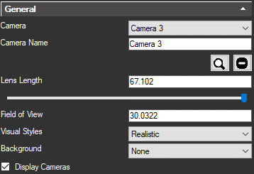
Camera: Select a camera by name from this pull down.
Camera Name: View or Edit the name for selected camera.
Magnifying Glass icon: Select to enable perspective view mode and set the current camera as your drawing view.
Delete icon: Select to delete current camera.
Lens Length: Modify the Lens Length of selected camera by typing a value in millimeters or adjusting the slider.
Field of View: The field of view property sets how wide and tall the view is. Field of view would be analogius to the size of a movie screen. Large simulates the Edit the Field of view property. Larger values equate to a wider view.
Visual Styles: Select the Visual style visible when the camera is selected.
Background: Set a colour, Gradient of colours or jpeg image to be displayed behind CAD entities.
Display Camera: Set option to display cameras icons in the drawing. If this option is off the camera will not be visible and can not be modified using grips.
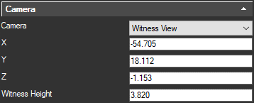
Camera: Select whether to treat this camera as:
Static: View origin will be the exact X,Y,Z coordinates displayed.
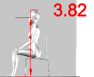
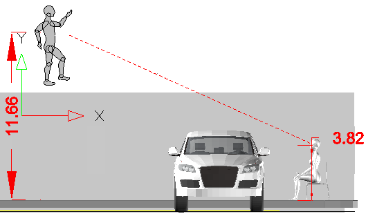
Witness View: View origin X,Y,Z coordinates displayed will be modified by the vertical offset defined in "Witness Height." This allows simulation of eye height when developing a view from a map.
Camera Name: View or Edit the name for selected camera.
X,Y,Z coordinates: Coordinates of camera
Witness Height: (Displayed only for "Witness View" cameras) Set a vertical offset for the view origin. For example: Vertical distance from the ground to the center of the eye of a person whose view we are simulating.
Roll Angle: (Displayed only for "Static" cameras) Angular value to specify tilt of the camera from horizontal.
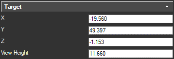
X,Y,Z coordinates: Coordinates of target.
View Height: (Displayed only when "Witness View" camera option selected) Set a vertical offset for the target. For example: Vertical distance from the ground to the object a witness reported viewing.
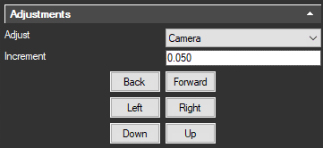
Adjust: Select camera or target to adjust coordinates
Increment: Set number of units that will be applied to X,Y or Z coordinate for each mouse click.
Back/Forward: Adjust camera to target distance by modifying coordinates of camera or target.
Left/Right: Adjust camera to target direction by modifying coordinates of camera or target.
Down/Up: Adjust camera to target vertical direction by modifying coordinates of camera or target.