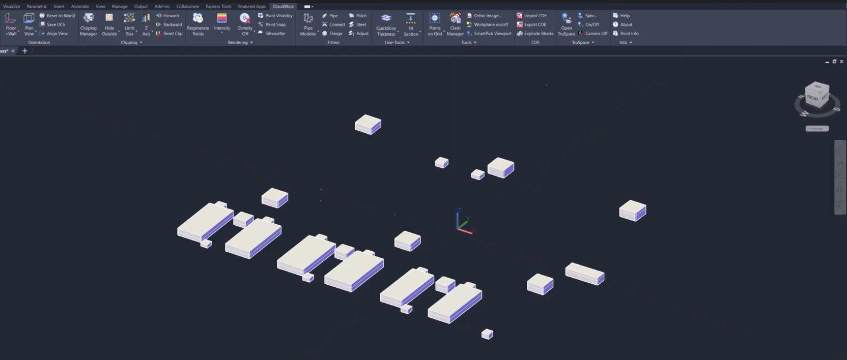
This guide is the first in the Plant Series Workflow Guides.
It introduces the end-to-end workflow for extracting concrete footing outlines in CloudWorx for AutoCAD using the Line tools and converting the resulting 2D geometry into 3D solids.
Practice Data
Exercise CAD file (.dwg format)
Initial Setup
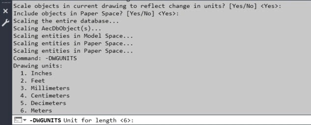
1. Verify the DWG units are set in meters by typing DWGUNITS in the command line.
-
In the Project panel, click Open LGSx File and load the required dataset (refer to the Open LGSx File Help page for more details).
.png?cb=f15e3b605345880ba734dea276701f59)
Clipping the Area of Interest and Isolating Foundations
To speed up point cloud processing, temporarily hide unnecessary points so you can focus on the area of interest and avoid unintentionally selecting points outside of it.
Creating Fence
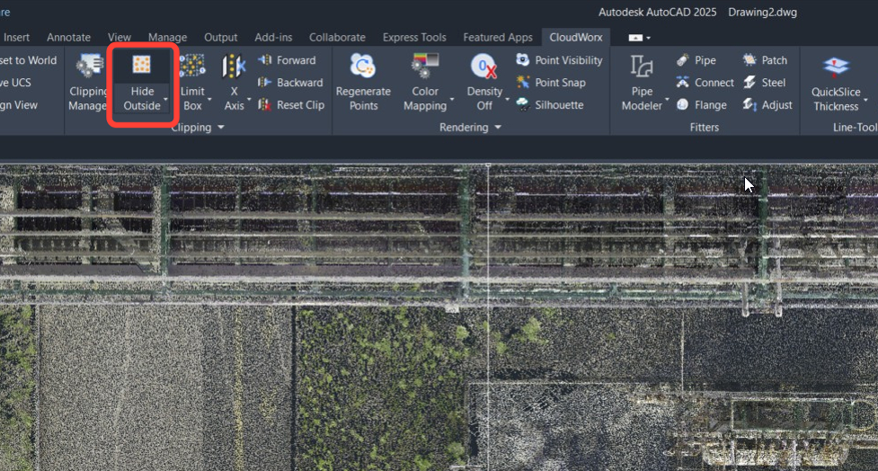
3. Navigate to Clipping | Fence | Hide Outside or type CWHIDEOUT in the command line.
-
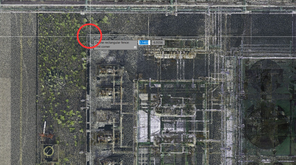
Following the prompts in the command line, select the necessary points for creating the chosen fence type. In this example, the Rectangular option is used.
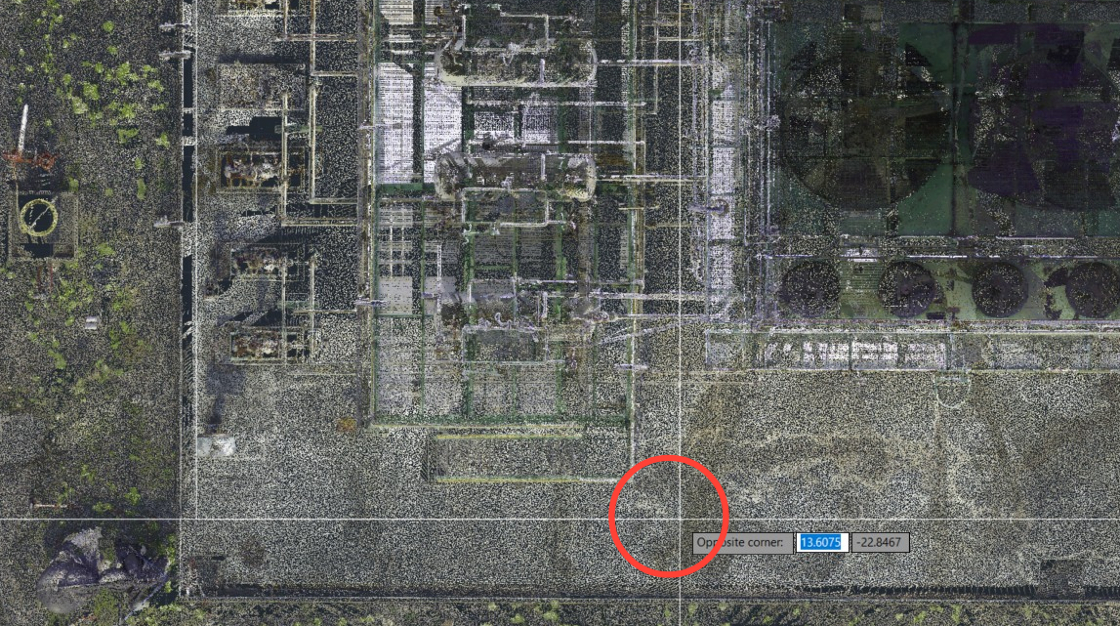
Creating QuickSlice
To prepare the data for use with the polyline tools, it is necessary to create the QuickSlice first. Let’s create a horizontal slice from a single pick point.
-
Navigate to Line-Tools | QuickSlice Wall.
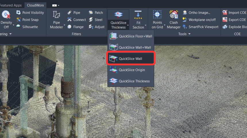
-
Select a point on the pump foundation.
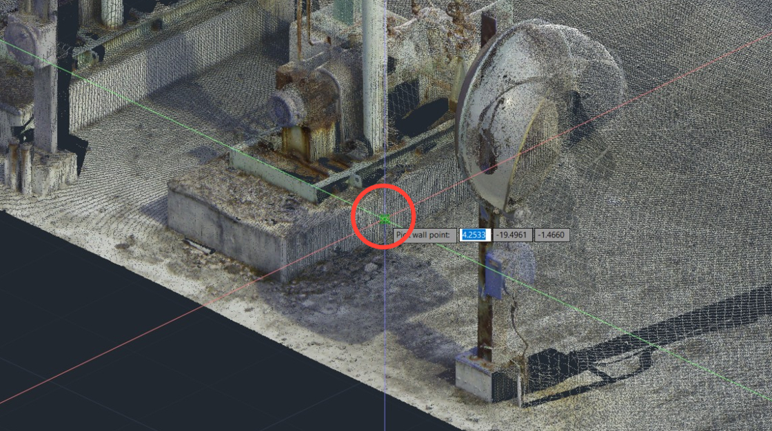
-
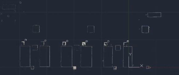
The created slice is too thick to see the outline of each foundation. Decrease the slice thickness to better isolate the foundations: select QuickSlice Thickness from the QuickSlice drop-down and set it to .1.
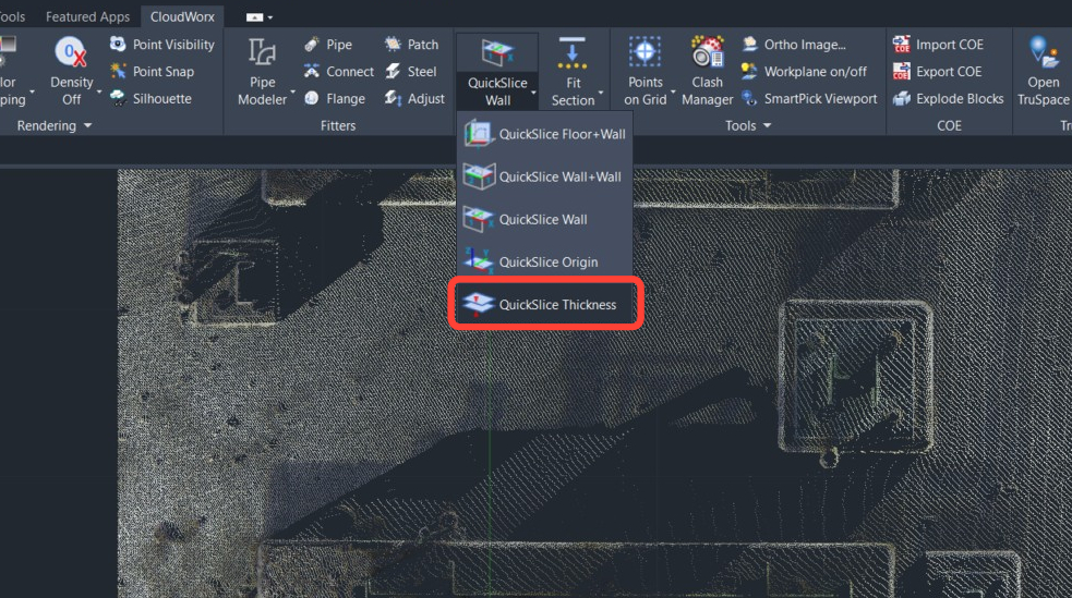
The outlines of each foundation become clearer, although additional refinement is still required for accurate extraction.
Adjusting Cloud Color
-
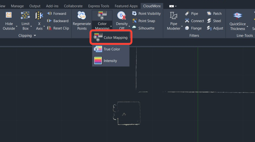
To improve the visualisation of foundations, navigate to Rendering | Color Mapping.
-
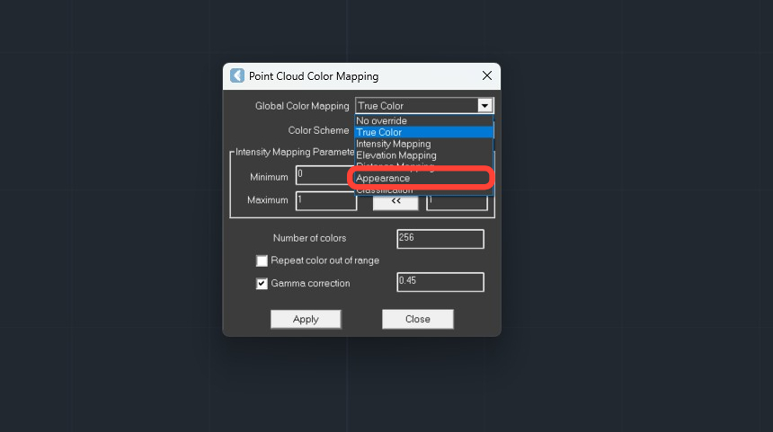
In the Point Cloud Color Mapping dialog, select Appearance from the Global Color Mapping drop-down list.
-
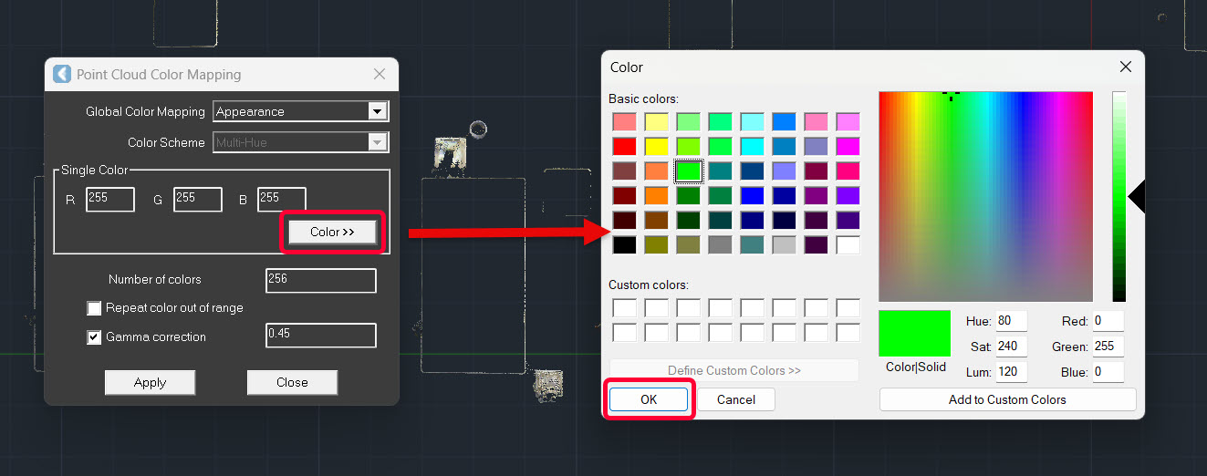
Click Color, select a high contrast color, and click OK.
-
In the Point Cloud Color Mapping dialog, click Apply to save the changes and then close the dialog.
Extracting Foundation Linework
In this section of the workflow, we will examine various methods for extracting linework using the Line tools.
Using 2Point Polyline Tool
In areas with obstructing features, it is recommended to use the 2Point Polyline tool for greater control when creating foundation geometry.
-
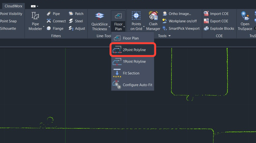
Navigate to Line-Tools | 2Point Polyline.
-
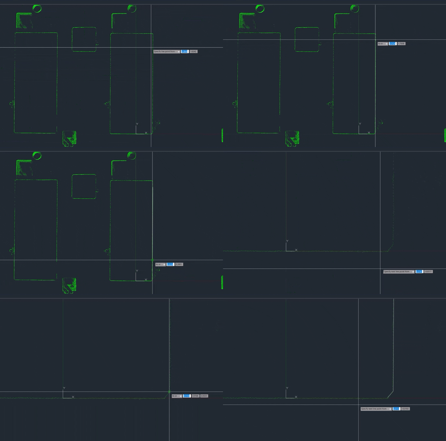
Select two points on a linear section of the point cloud. The system will then generate a fitted line.
-
Proceed by selecting two points on the subsequent linear sections. The previous segments will connect automatically to form a polyline.
-
To close the polyline, type C and press Enter.
Note: When using the 2Point Polyline tool on very noisy datasets, the grow feature may produce undesirable results after the second point is selected, making it difficult to fit the linework to the cloud.
Here are several ways to help fix this:
-
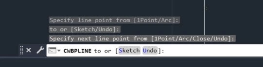
To undo the command, click in the console or type U, then the spacebar or Enter.
-
If only the first of two points is selected in the 2Point Polyline command, undoing the command removes the initial point selection.
-
If there is no active point selection, the Undo function will delete the last polyline segment drawn.
-
-
The Sketch option becomes available after selecting the first point in the 2Point Polyline command. If the Sketch option is chosen, the second point will disregard the point cloud and autofit will be disabled. The second point will be placed precisely where you click on the screen, and the segment's endpoints will correspond to your selected points.
Using Created Polyline as a Template
Since many concrete forms are similar in size and shape, you can reuse an existing polyline as a template and then adjust it to fit the point cloud.
Tip: To achieve more precise control when fitting objects to the point cloud, ensure point snapping is disabled (Rendering | Point Snap).
-
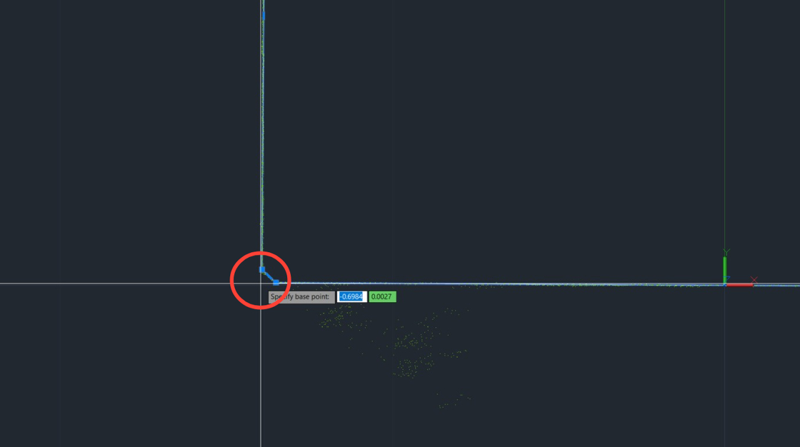
Select the previously created polyline and enter COPYBASE. Then, click the corner where the two longer lines would intersect. You can hover your cursor over the lines to find the intersection.
-
Use the mouse wheel to pan to the next concrete form where you will apply the copied polyline. Then press Ctrl+V and click the corresponding imaginary corner to insert the polyline.
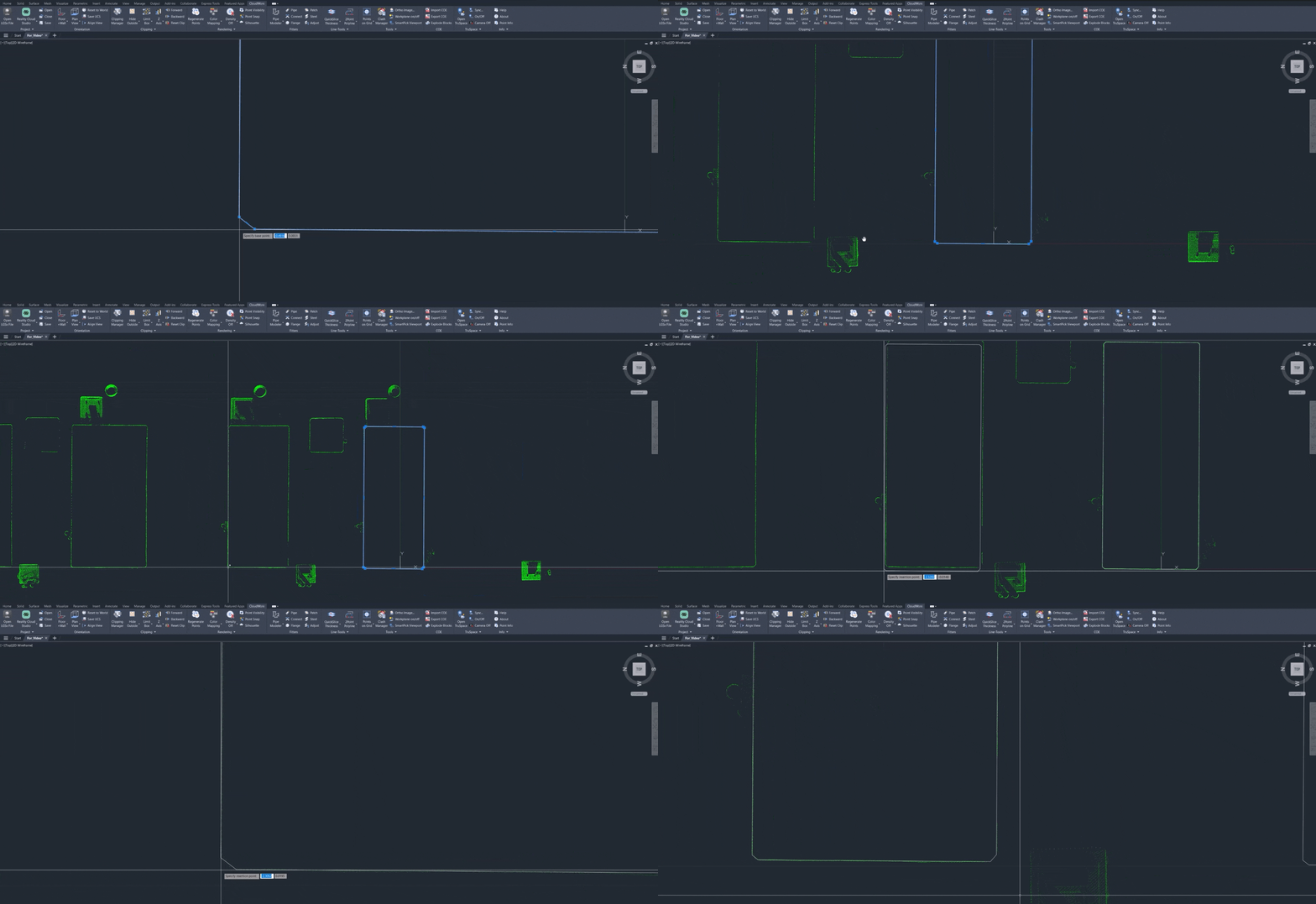
-
Drag the vertices of the polyline as needed to align with the point cloud.
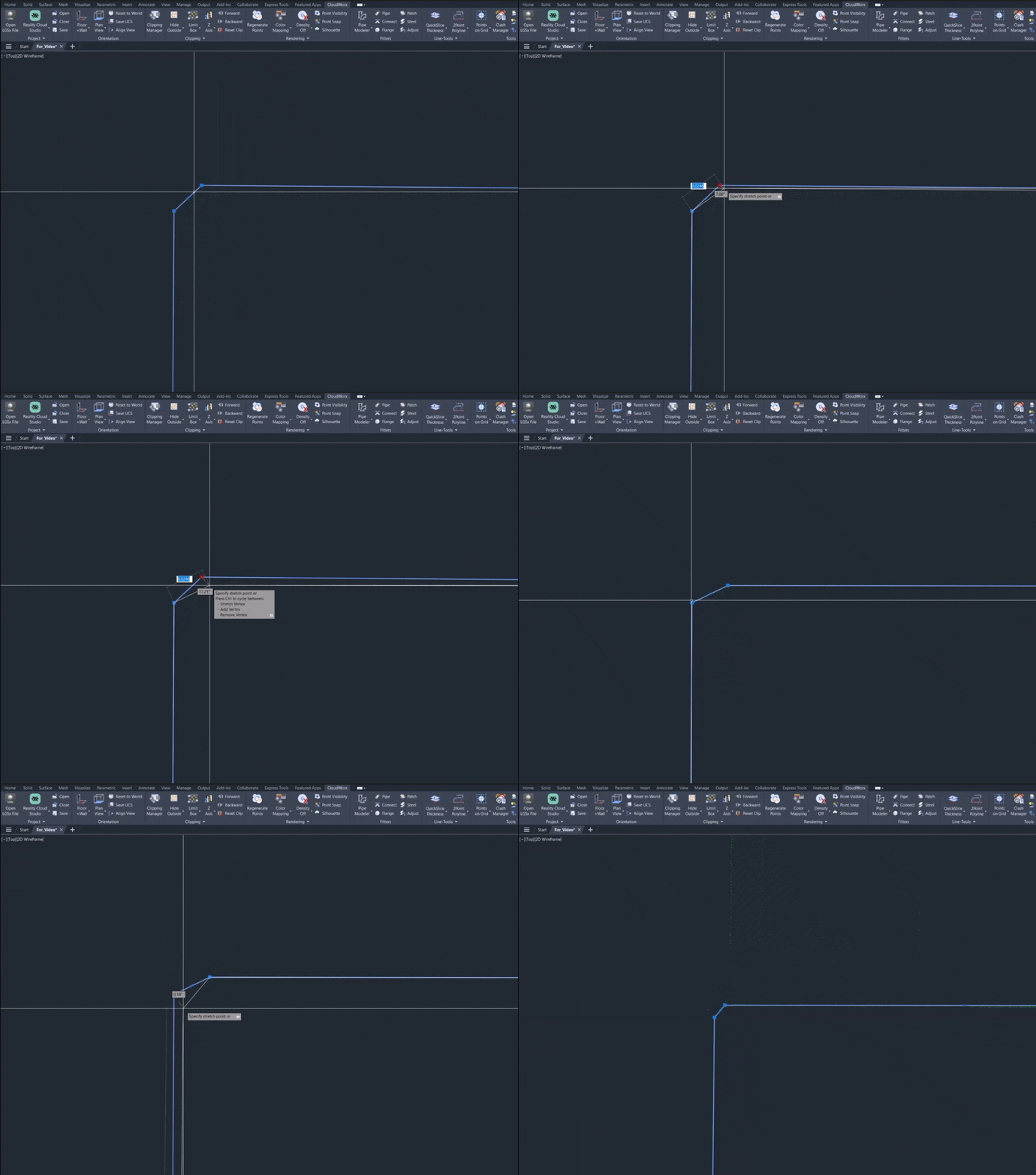
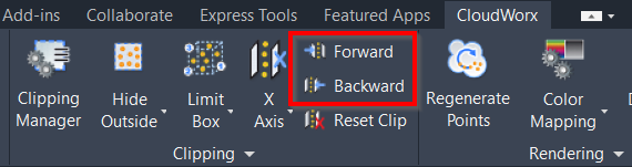
Tip: When adjusting a polyline, you might notice that some areas are hard to see because of shadows or unclear spots. This can lead to slices with limited or missing data. To fix this, try moving the clip forward or backward along its perpendicular axis. This way, you can find a slice area with enough data to adjust the polyline.
-
Repeat Steps 16-18 for the remaining pump forms.
Switching Between 1Point and 2Point Polyline Tools
While the 2Point Polyline tool is well-suited for obstructed or noisy areas, the 1Point Polyline tool is typically used in low‑noise regions, where it can automatically fit or grow a segment with a single click. In the following steps, let’s extract the remaining pump foundation linework using a combination of 1‑point and 2‑point polylines.
-
Navigate to Line-Tools | 1Point Polyline and click a linear section of points.
-
The line segment is automatically grown.
-
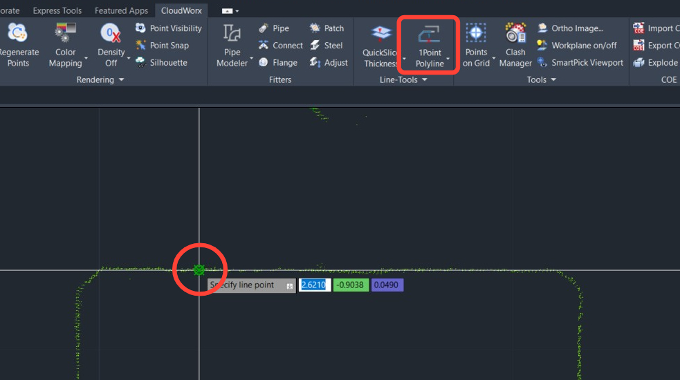
-
When creating the shape's corners, switch to the 2Point Polyline tool. While the command is active, press 2 and then press the spacebar.
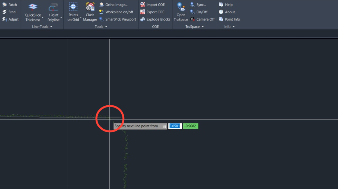
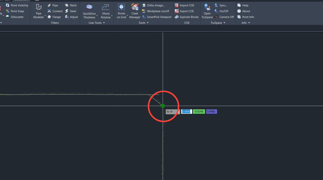
-
Switch back to the 1Point Polyline tool by typing 1 and pressing the spacebar, and continue creating polyline segments.
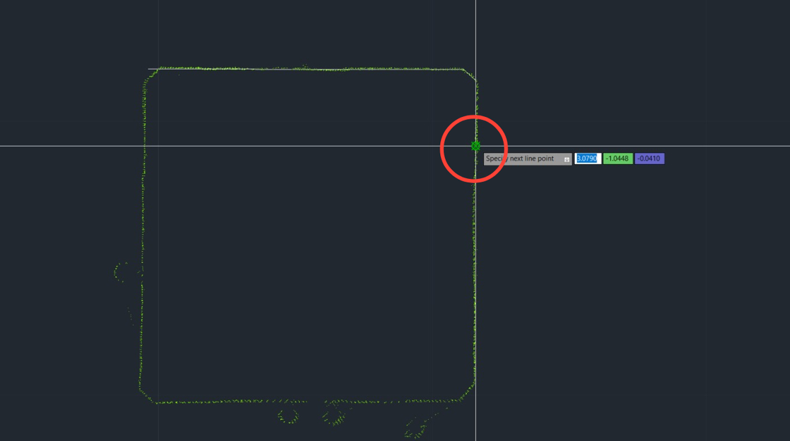
-
In one-click mode, the polyline grows until the algorithm can no longer match the point cloud, which may result in incorrect linework. To remove unwanted segments, press U and then press the spacebar.
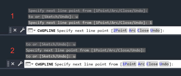
Note: You can easily switch between the two modes by using the keyboard or by clicking the options given in the command line.
The active option is the one not shown in the command line.
In the first image, the tool is in 1Point mode; in the second, it is in 2Point mode.
Using Fit Section Tool
In low-noise areas, the Fit Section tool can help speed up line adjustment.
-
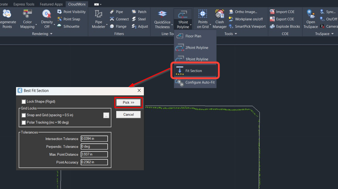
In the Line-Tools panel, select Fit Section from the drop-down list and then click Pick in the Best Fit Section dialog.
-
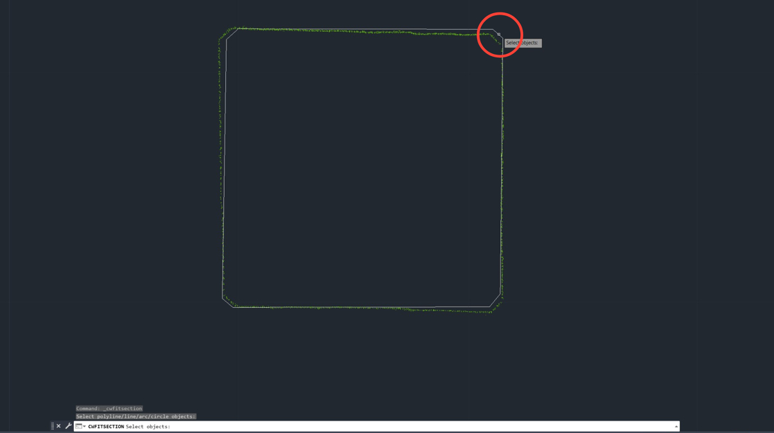
Select the polyline and press Enter.
-
The linework will be automatically adjusted to fit the point cloud.
-
-
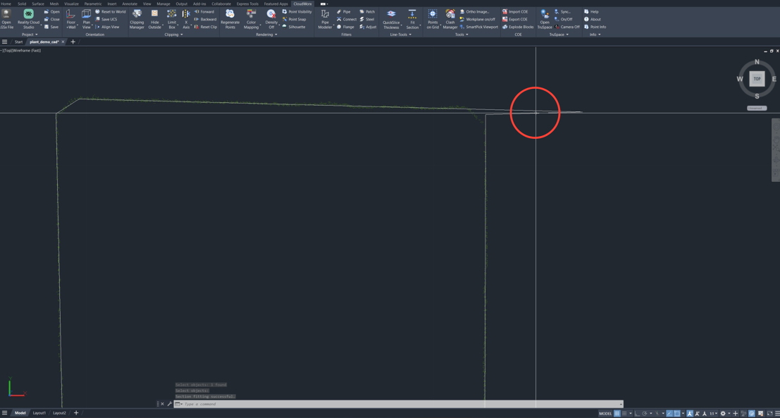
Check that the adjustment is accurate. In this example, the tool adjusted the section well, except for one vertex that needs manual correction. Select the stretch point to make this adjustment.
.jpeg?cb=46ec939339a84c6dae94d653457f5ac0)
-
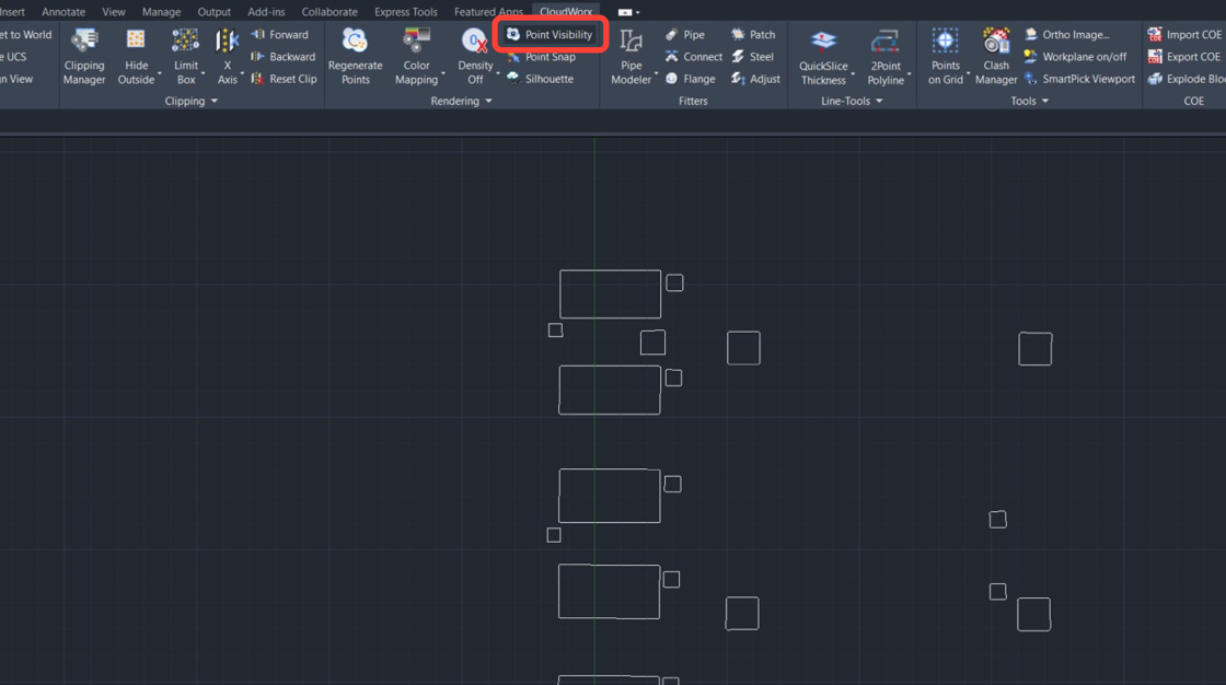
Navigate to the Rendering panel and turn off Point Visibility to review the extracted linework.
Converting 2D Linework into 3D Solids
Now, when the linework is extracted, let’s create 3D solids for the foundations based on it.
Initial Preparations
-
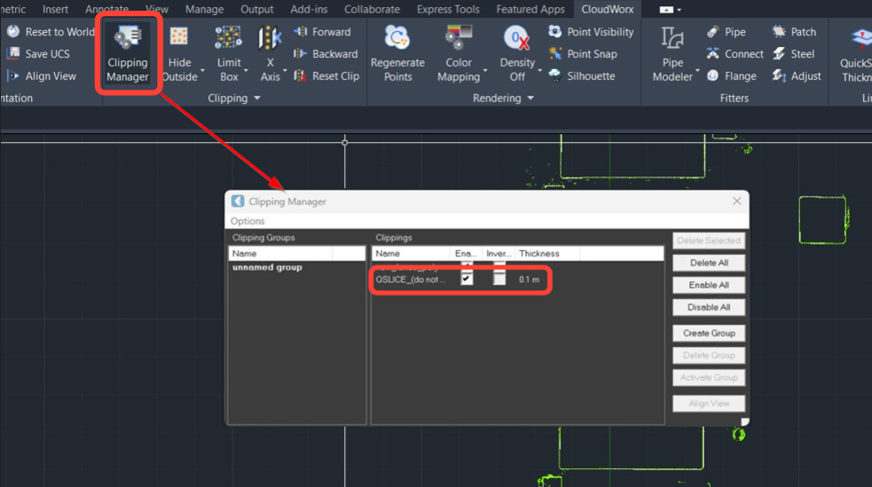
Navigate to Clipping | Clipping Manager and disable the previously created QuickSlice by deselecting the check box next to it.
-
Create a new slice:
-
Rotate the view to a profile view using the View Cube and select the Z-axis slice tool in the Clipping panel.
-
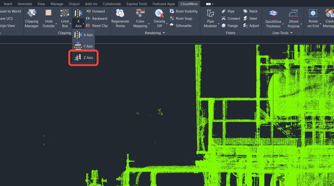
b. Create a slice by defining two parallel planes along a specified axis.
-
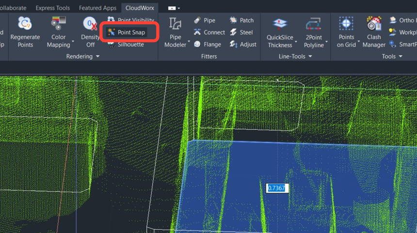
Verify point cloud snapping is enabled by clicking Point Snap in the Rendering panel.
-
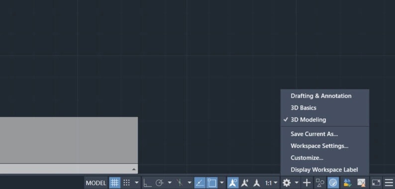
To create 3D objects efficiently, switch the workspace to 3D modelling: click the gear icon in the lower-right corner of the AutoCAD window or enter the WSSETTINGS command and select the desired option from the drop-down.
The 3D Modeling workspace updates the ribbon layout, providing easier access to solid creation and editing tools.
Using Presspull Command and SmartPick Viewport
-
Rotate the cloud to an oblique view and click SmartPick Viewport in the Tools panel.
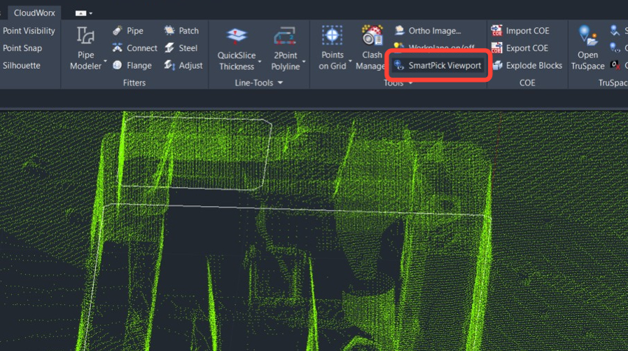
Info: The SmartPick Viewport enables smart picking control and offers a zoomed, spotlight view of the point cloud around the mouse cursor.
-
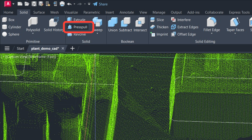
Navigate to the Solid tab and click Presspull. This command extrudes a solid from 2D linework in whatever direction the user chooses.
-
Click the form outline, then click the Rotate View button in SmartPick View several times until the view shows a profile of the concrete footing.
.jpeg?cb=26474fb4cd6ffe12dc97b06596544dce)
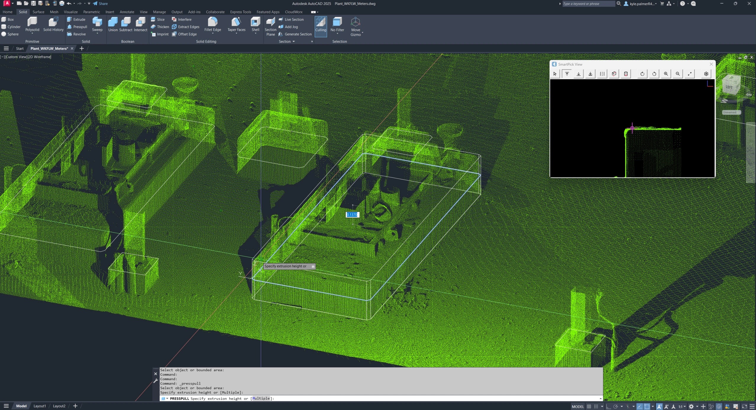
Important: The SmartPick Viewport will not display any points unless an active command that requires point selection is running, such as PLINE or PRESSPULL.
-
Begin by extruding the linework to the base of the concrete footing:
-
In SmartPick View, click Ground to set up the pick for the bottom of the form.
-
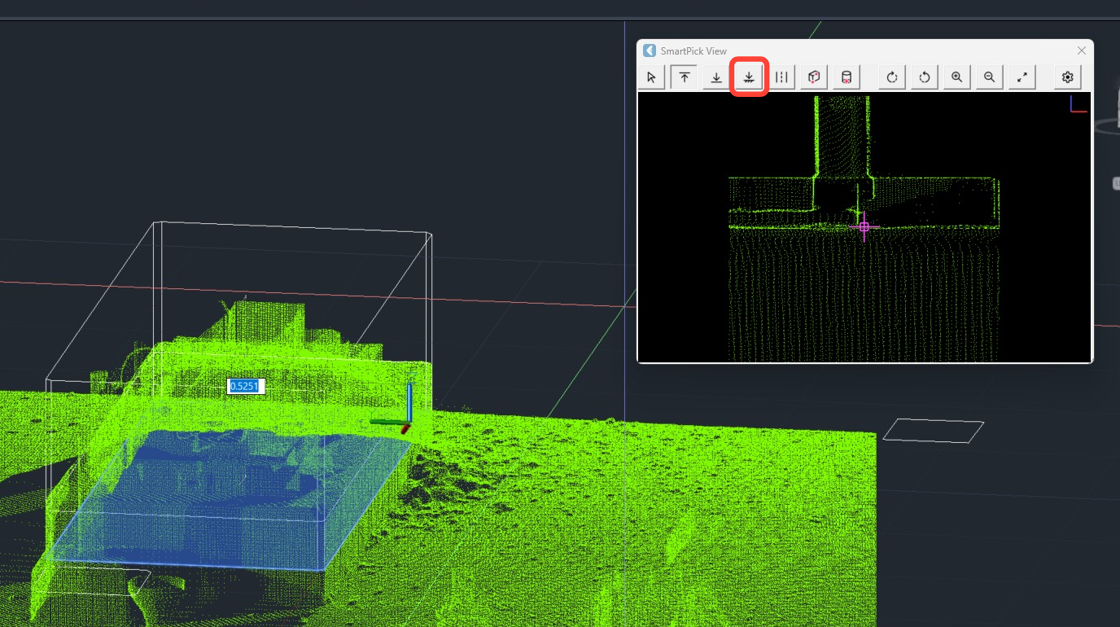
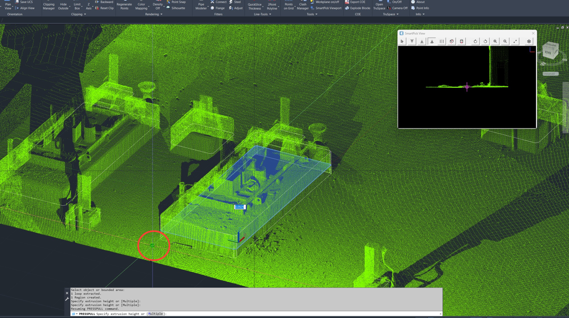
b. Look for the magenta cursor in SmartPick Viewport. When you hover over points in the ModelSpace, the ground algorithm evaluates nearby points to select the most suitable one. This reduces the need for precise selection and helps prevent accidental picks on noisy points.
c. Click on the ground near the footing.
-
Now, let’s extrude the solid so it lines up with the top of the concrete footing:
-
In SmartPick View, click Highest.
-
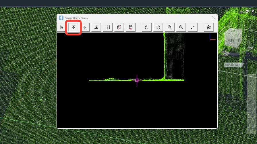
b. Select the top of the solid and then click the top of the concrete footing.
-
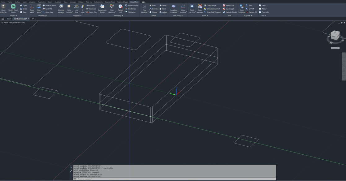
Close the SmartPick View dialog and turn off the point visibility to view the created 3D solid.
-
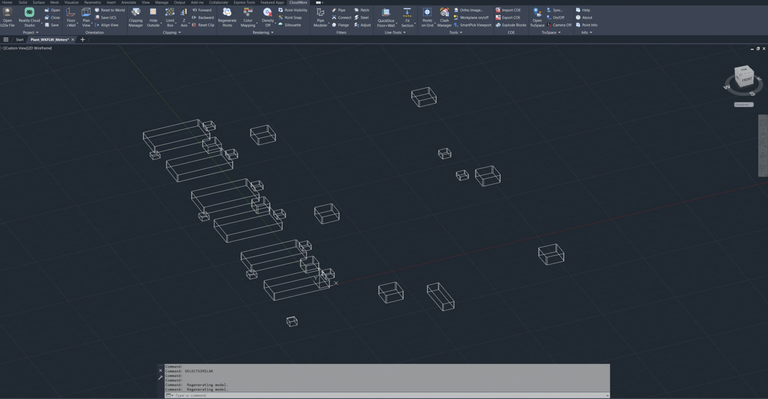
Repeat the previous steps for the remaining forms. The final result should match the example shown in the image below.
-
To better visualize the result, switch to the Visualize tab and set the view mode to Conceptual for all solids.