
This guide concludes the Plant Series and outlines several methods for creating an open or blind flange at the end of a pipe. The workflow involves extracting flange geometry and calculating a work point to facilitate alignment of the design model with existing features. In this example, the flange will be positioned at the open end of a valve and then connected to a pipe.
Prerequisite: For full workflow context and results, review the preceding guides in this series:
Practice Data
Exercise CAD file (.dwg format)
Clipping the Area of Interest
-
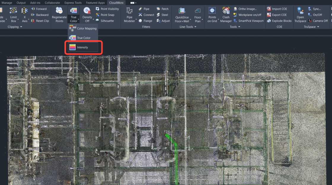
In the Rendering panel, set Color Mapping to Intensity.
-
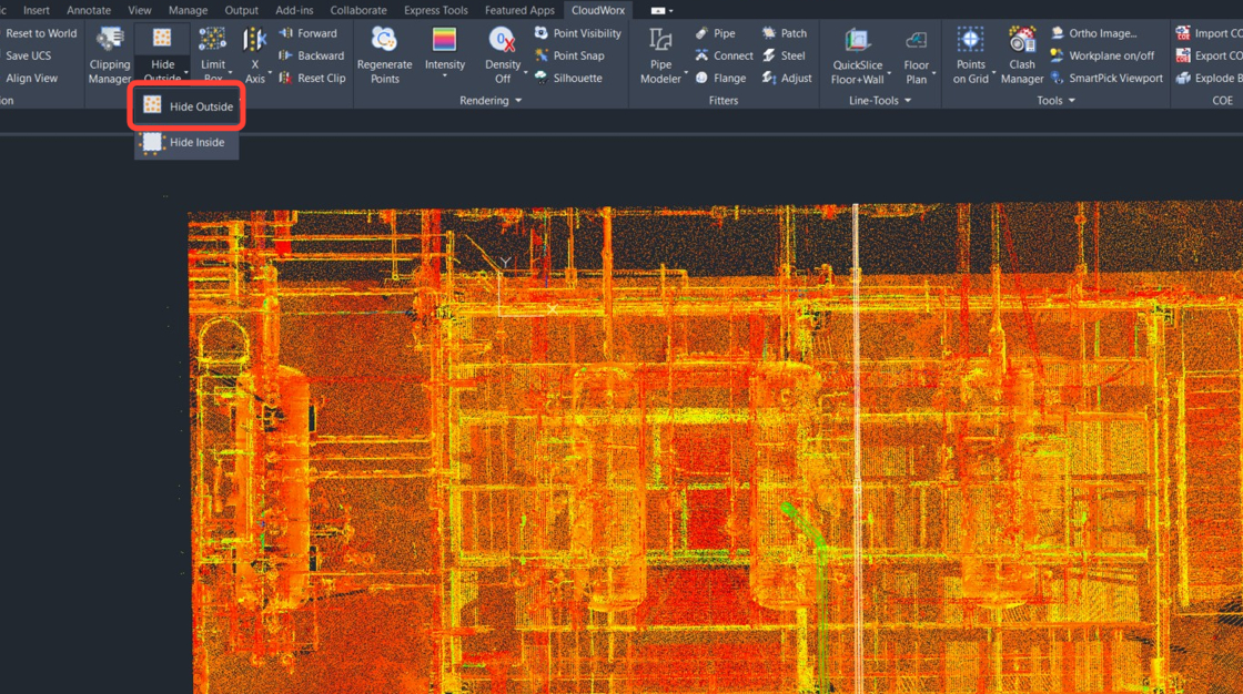
In the Clipping panel, click Hide Outside or type CWHIDEOUT in the command line.
-
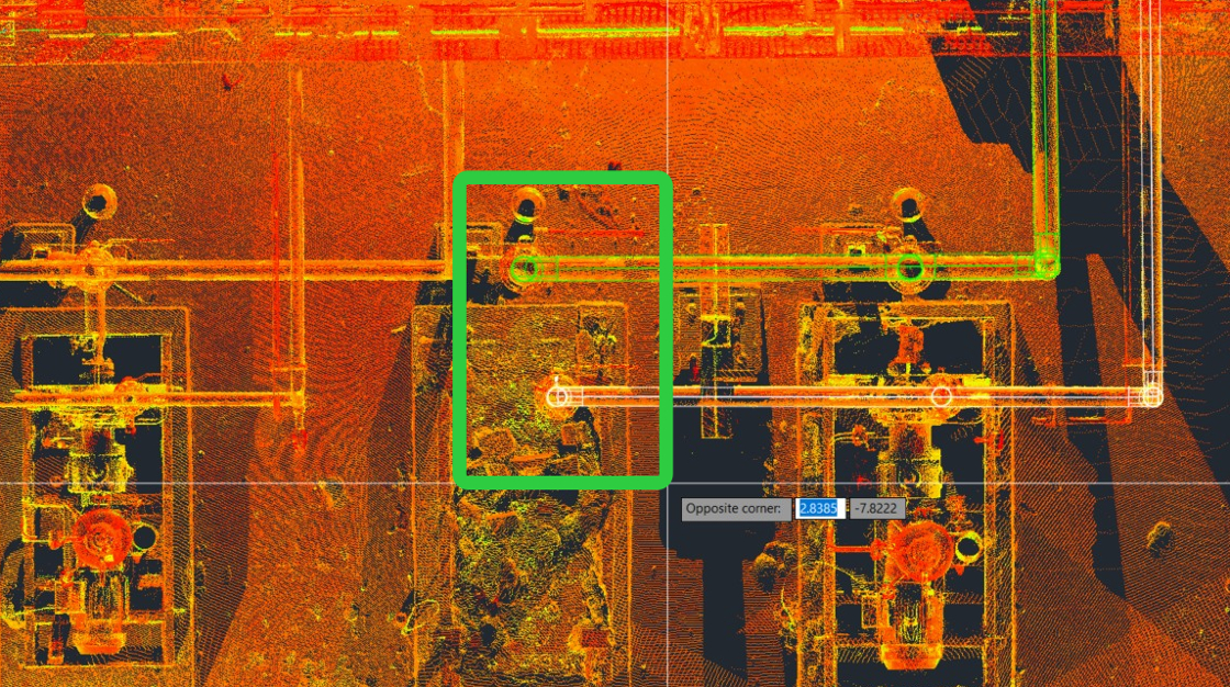
In the command line, select Rectangle ot type R, then follow the prompts to draw a rectangular fence around the area of interest. Press Enter to complete fence creation.
-
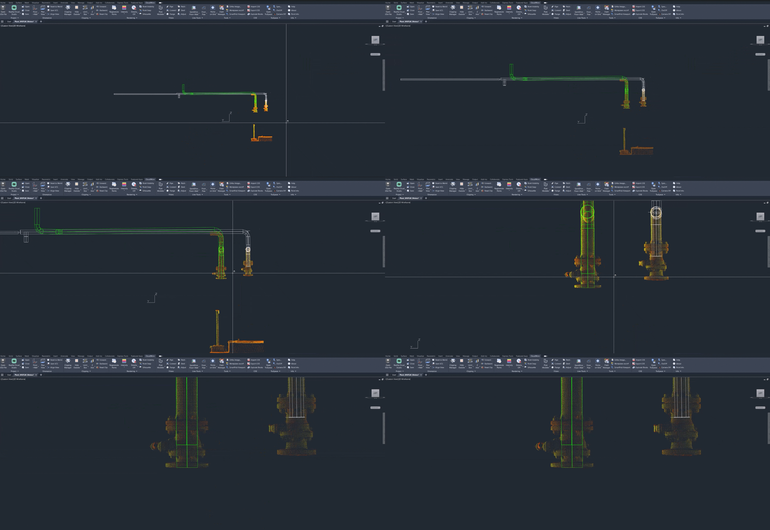
Rotate the view to the left and zoom in on the clipped area.
Extracting Flange Geometry
As shown above, the pipe runs terminate at valves. To ensure the model aligns accurately with the point cloud, this section outlines several methods for extracting flange geometry at the valve end.
Neighbor Method
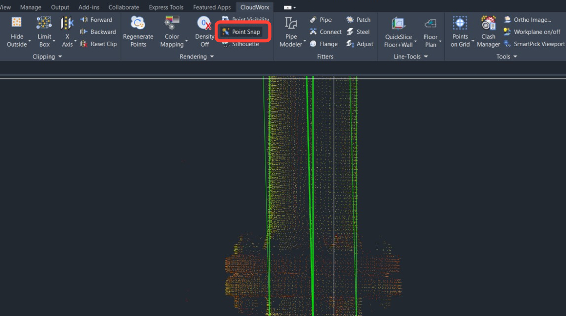
5. Ensure point snapping is enabled.
-
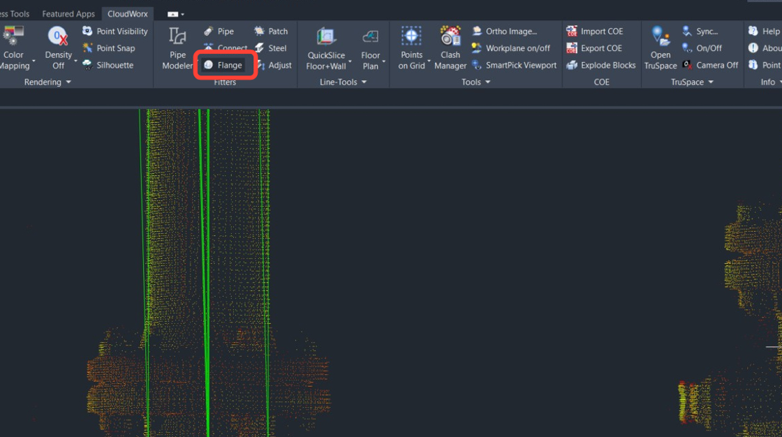
Enable the Flange fitter. Go to Fitters | Flange.
-
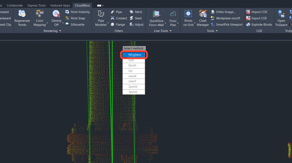
From the pop-up menu, select the Neighbor method.
-
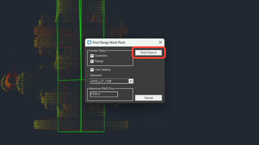
Configure the fitter as follows:
-
Select the Centerline check box.
-
Select the Flange check box.
-
Select the Use Catalog check box and then select the required catalog. In this example, it’s ANSI_LJT_150#.
-
-
Click Pick Point.
-
First, pick a point on the neighbor pipe segment to which a flange is connected.
.jpeg?cb=49b4fc944de37195e2e8187882c82275)
-
Then click a point on the edge of the flange.
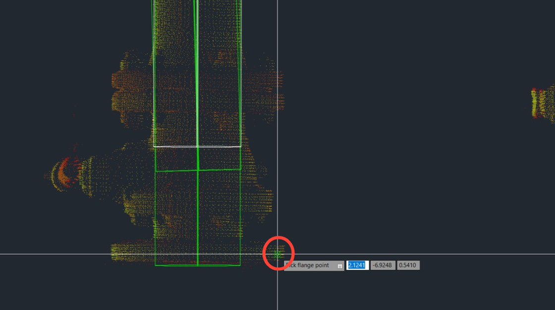
-
Verify the catalog fit and click OK.
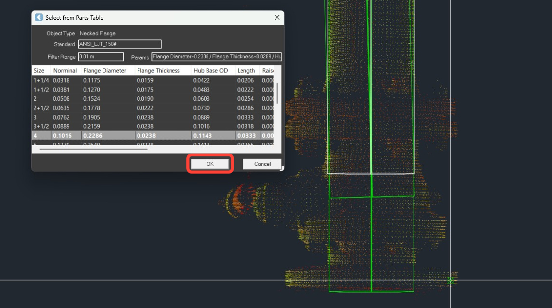
-
Select the position of the flange face, which is typically the lowest point. Press Enter.
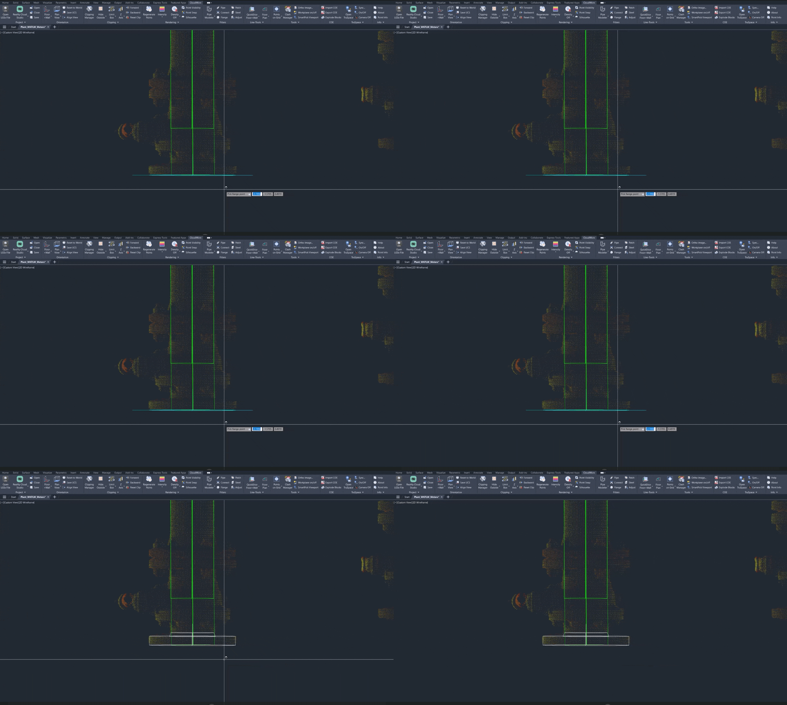
The flange is now created and placed at the end of a valve.
3 Point Method
-
Enable the Flange fitter and select the 3point method.
.jpeg?cb=3e68c2dfd402823c6f0d38f6031bce4b)
-
Check the selected configurations (see Step 8) and click Pick Point.
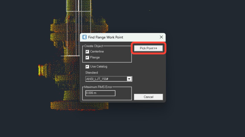
-
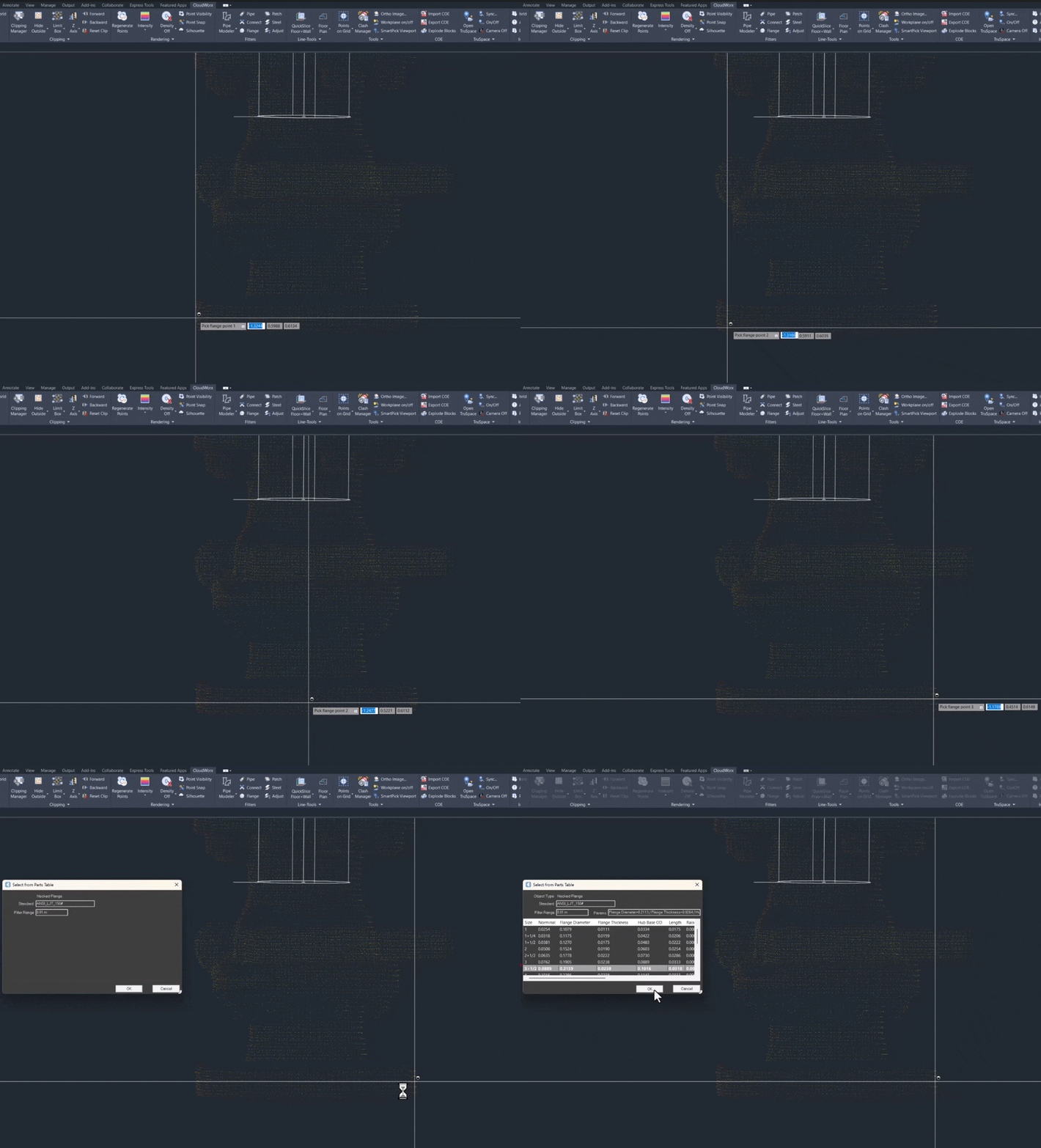
Select three points along the edge of the flange. Then, verify the catalog fit and click OK.
-
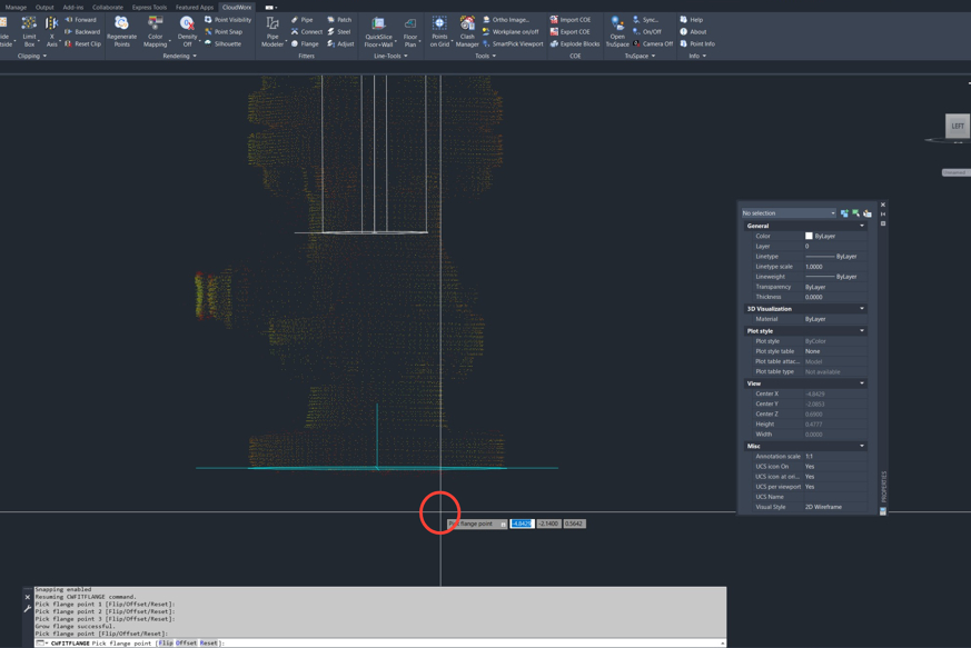
Select the position of the flange face, which is typically the lowest point. Then, press Enter, and the flange will be created, and a work point will be calculated.
-
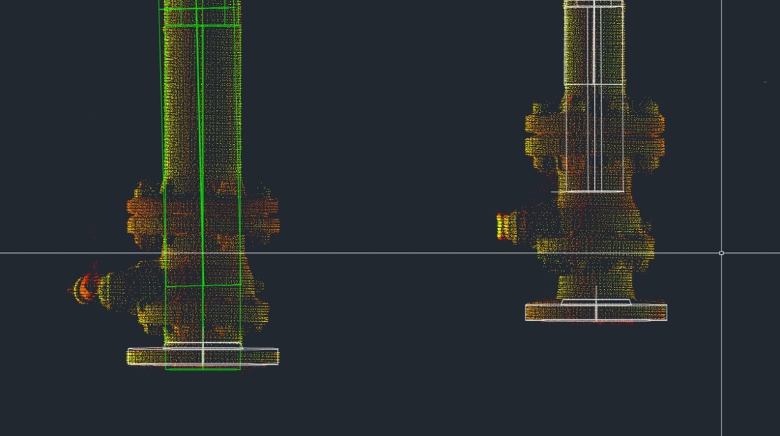
The flanges are now created and positioned at the valve ends. Notice that they are not directly attached to the adjacent pipes; however, they align correctly with the final pipe segments connected to the valve. For the purposes of this exercise, the valve is ignored. The goal is to obtain a work point coordinate to position the design model.
Fitting Pipes to Flanges
To complete the workflow, let’s fit the pipe to the flange.
-
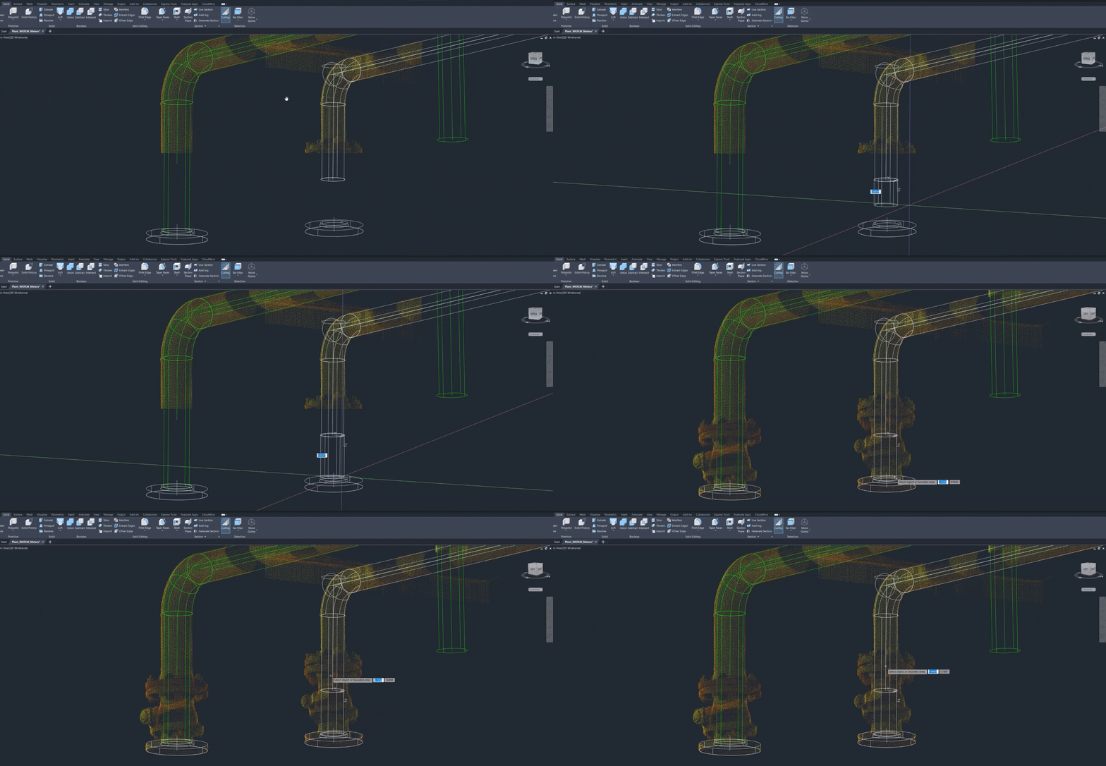
Go to the Solid tab and click Presspull.
.jpeg?cb=b9f3cf4ab52ef0a1dbbe2dbcec76b0f2)
-
Select each pipe end and extend it to the flange.
-
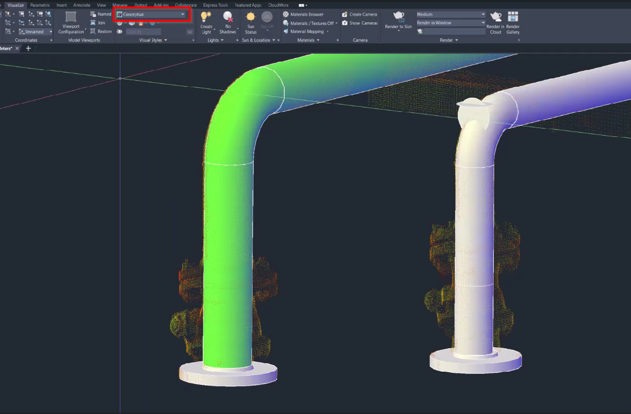
To review the result, change the visual style to Conceptual on the Visualize tab.
⬅️ Previous: Using the Pipe Modeler to Extract Pipes