
This guide explains how to extract pipe segments and create T‑branch connections using the Pipe Modeler tool.
Prerequisite: For full workflow context and results, review the preceding guides in this series:
Practice Data
Exercise CAD file (.dwg format)
Isolating Pipes to Extract
Before extracting pipe geometry, let's define the area of interest and adjust the color mapping settings to easily identify pipes in the point cloud.
Pipe Object Classification
-
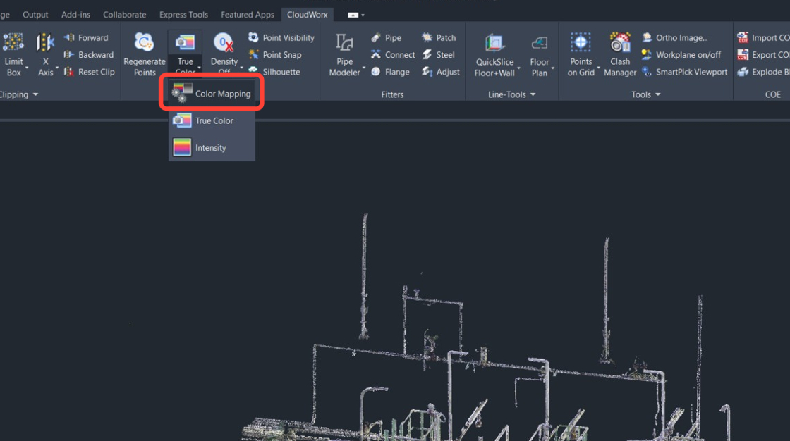
On the Rendering tab, select Color Mapping.
-
In the Point Cloud Color Mapping dialog, set Global Color Mapping to Classification and click Apply.
.jpeg?cb=59169889d9bc5df4ac05b690c7560775)
-
Click Class Visibility.
.jpeg?cb=361216d9b6ba92b99941bdc8e9ae9d61)
-
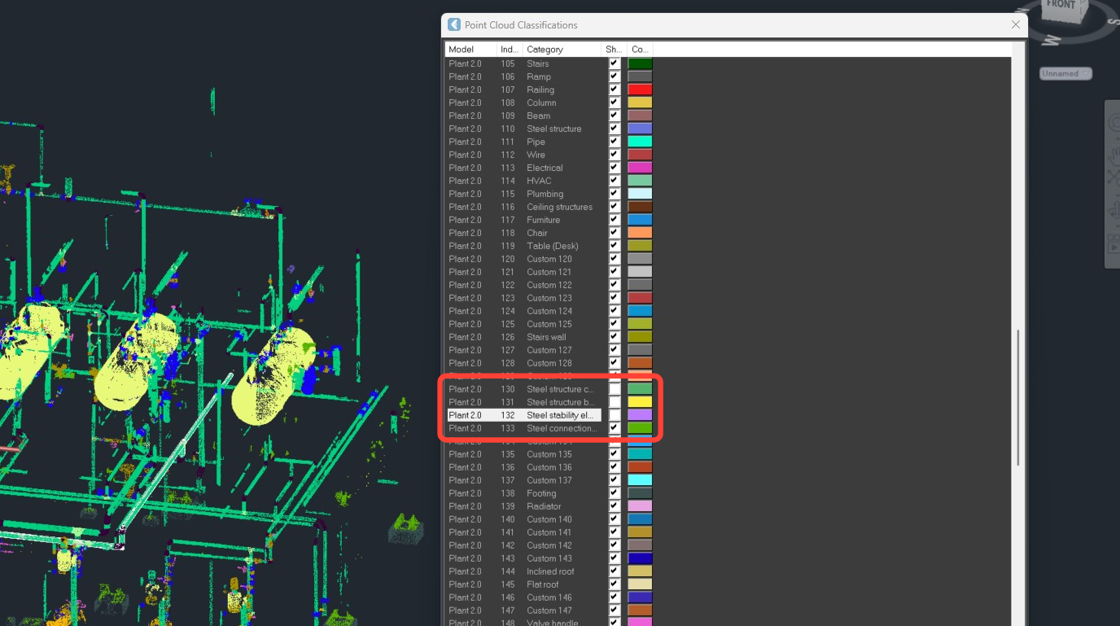
In the classification table, review the categories and deselect the ones listed below to make pipes and their connections stand out more clearly in the point cloud.
-
1 Unclassified
-
130 Steel structure column
-
131 Steel structure beam
-
132 Steel stability element
-
133 Steel connection element
-
-
Close the classification table and the Point Cloud Color Mapping dialog.
Clipping the Area of Interest Using Fence
-
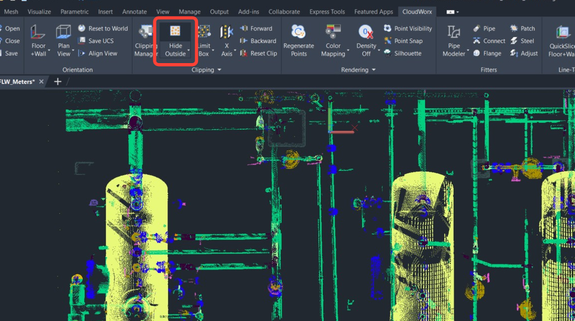
Navigate to Clipping | Hide Outside or type CWHIDEOUT in the command line. Then, switch to the polygon fencing mode by either selecting Polygon in the command line or typing P and pressing Enter.
-
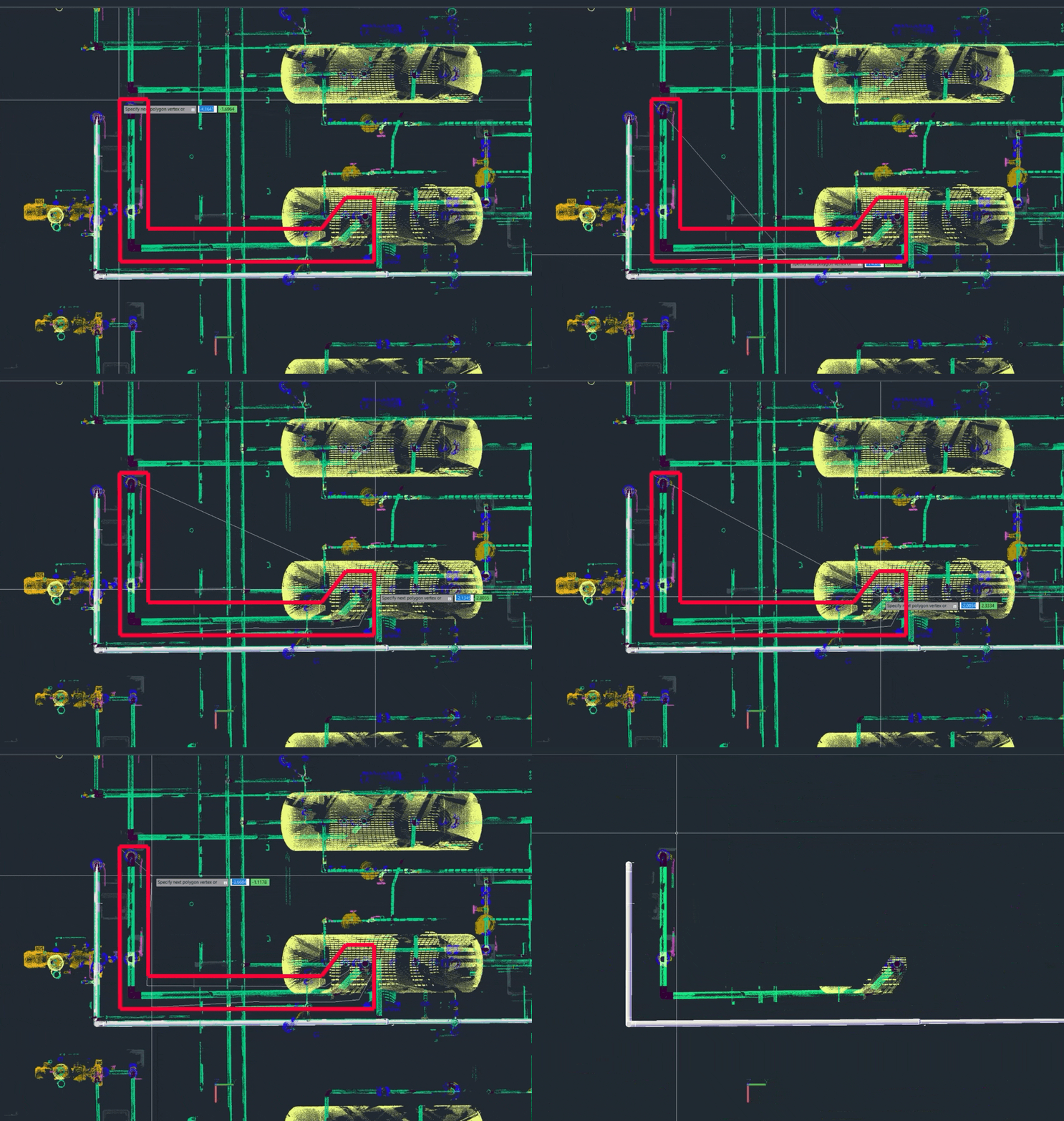
Draw a fence around the pipe run that should be extracted. When finished, press Enter.
Using Pipe Modeler Tool
This section of the workflow describes how to use Pipe Modeler, a semi-automatic tool designed for extracting the pipe geometry based on the selected parameters.
Extracting Pipe Run Geometry
First, let’s extract the segments of the pipe run isolated in the previous steps.
-
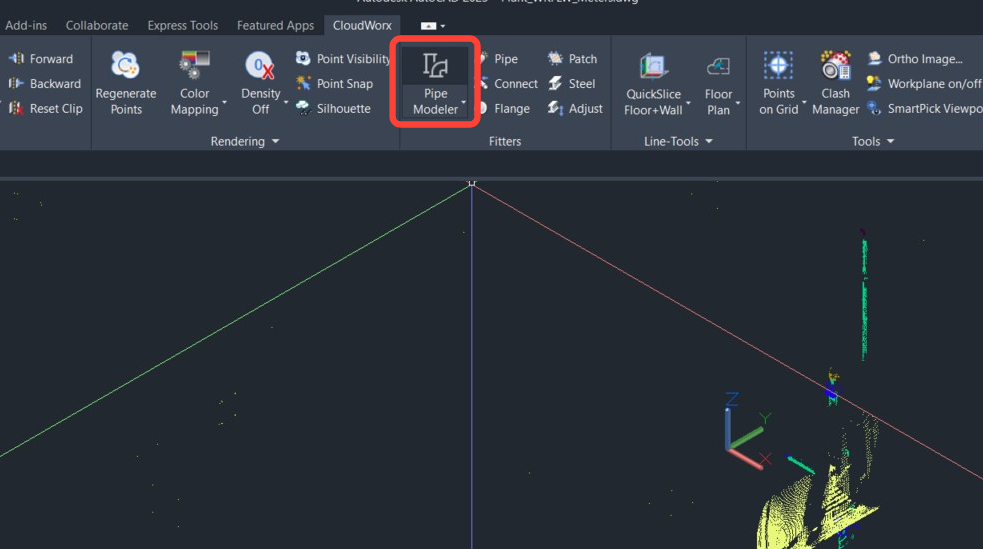
Go to Fitters and click Pipe Modeler.
-
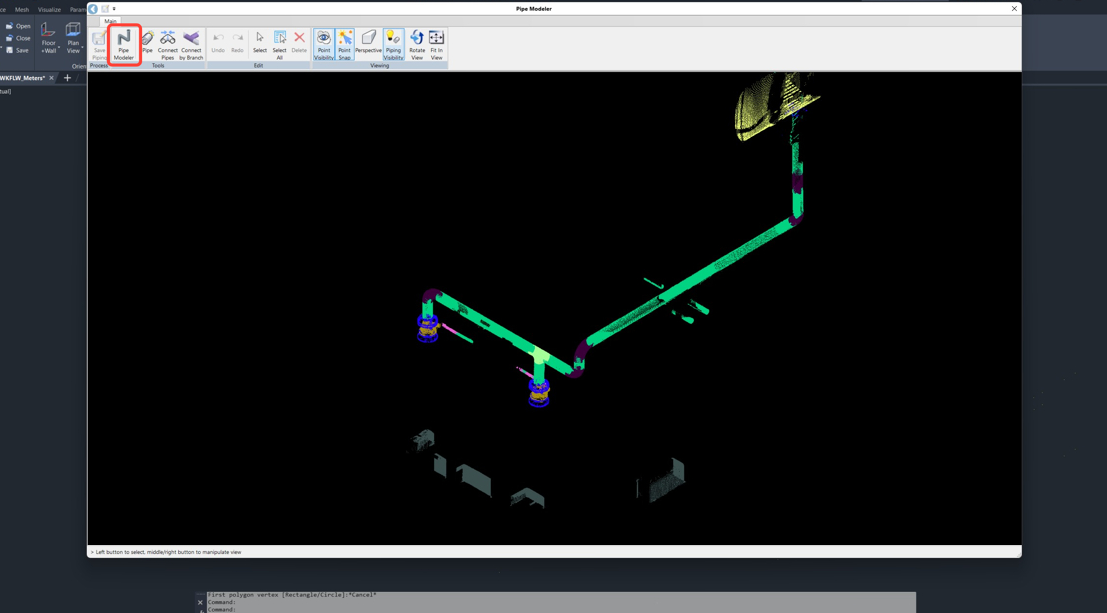
The Pipe Modeler will open in a new window. Click Pipe Modeler in the Tools panel.
-
Launching the Pipe Modeler tool updates the ribbon with additional options. In the PipeSystemTool panel, choose the following settings:
-
Select the Use Catalog check box and then select the required catalog. In this example, it’s ISO_GR1_PIPE-METRIC.
-
Set Bend Ratio to 1.3.
-
Select the Detect Elbow check box.
-
Select the Detect Branch check box.
-

-
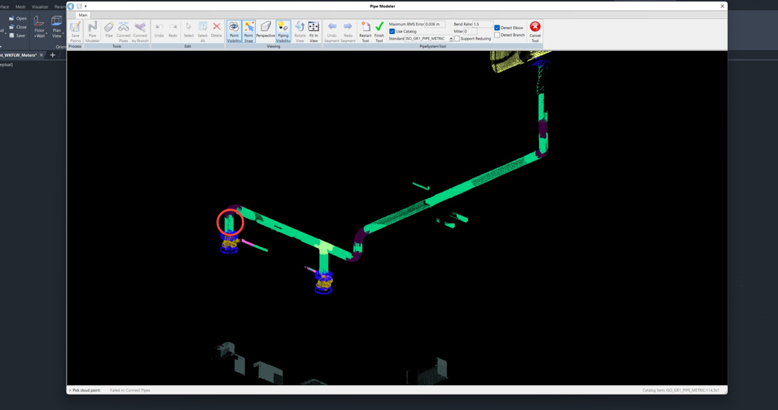
Click the start of the pipe run.
-
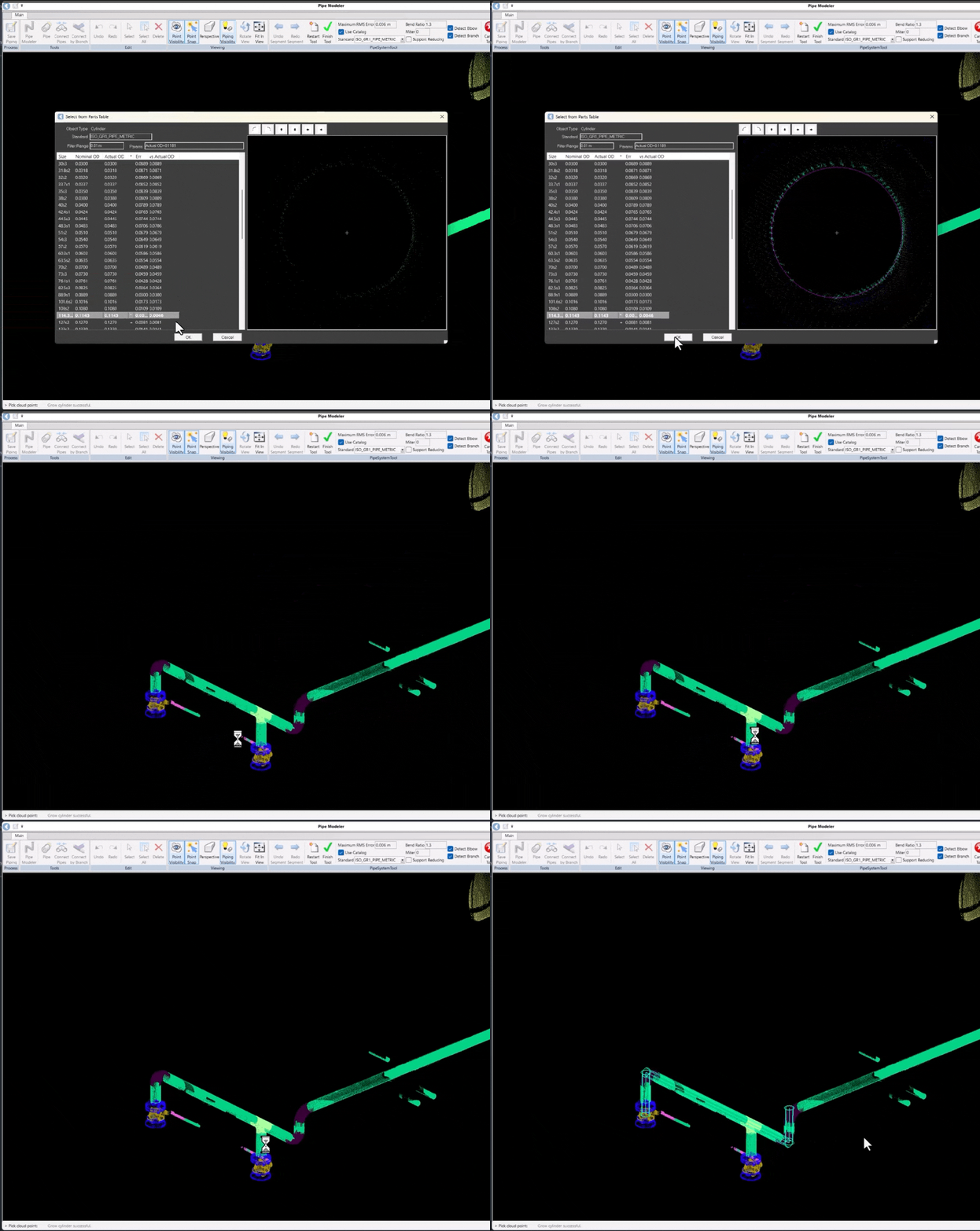
Verify the suggested catalog fit and click OK. The Pipe Modeler will grow the pipe run until a hint is needed.
-
Click the next pipe segment. This will provide the Pipe Modeller with the next hint to continue geometry extraction.
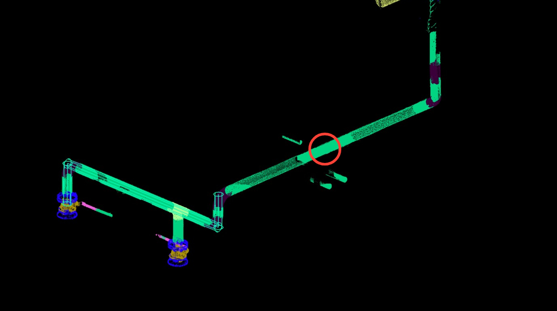
Tip: If the Pipe Modeler extends the pipe too far, click the Undo Segment button on the ribbon.
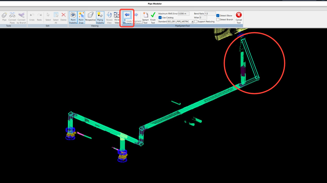
-
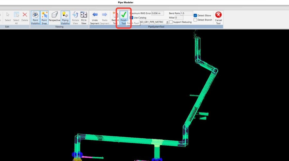
Continue clicking the remaining straight sections to complete the pipe run. Once finished, click Finish Tool.
Adding T-Branch Connection
Let’s proceed by joining the extracted pipe segments with a T-branch connection using the Pipe Modeler functionality.
-
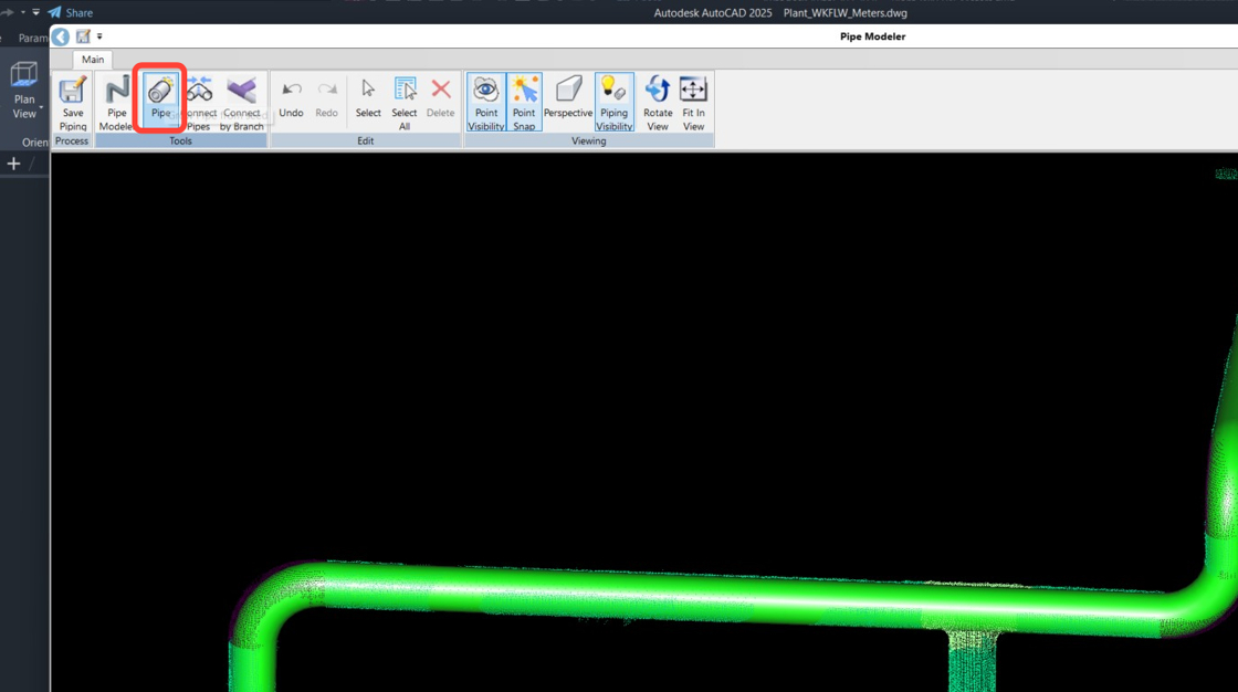
In Pipe Modeler, go to Tools | Pipe.
-
Click the branched pipe segment to extract its geometry.
.jpeg?cb=d12b836a603a2135cfe26152bcc44539)
-
Verify the suggested catalog fit and click OK.
-
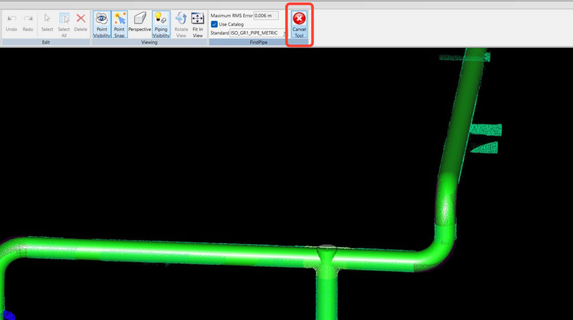
When the pipe segment is extracted, click Cancel Tool to accept the result.
-
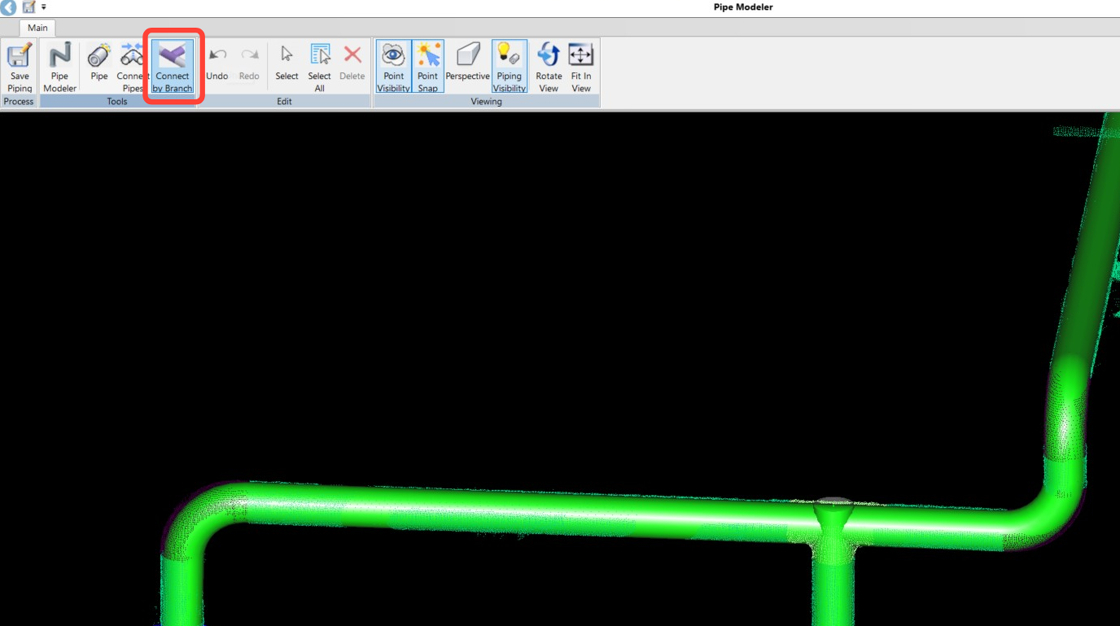
Now click Connect by Branch in the Tools panel.
-
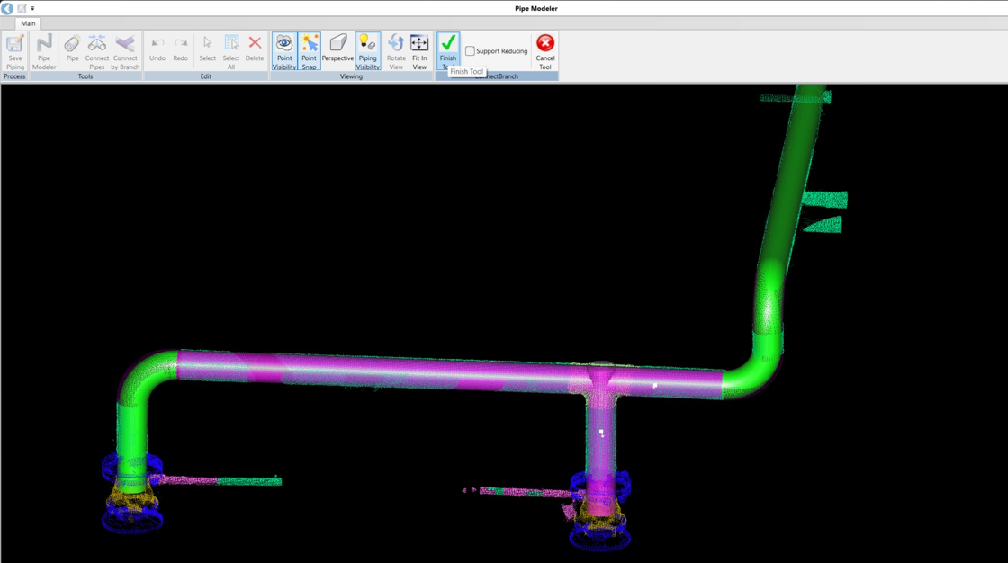
Select the main pipe system and the recently created pipe segment. Once selected, both will change to a magenta color, indicating they are ready for connection. Then click Finish Tool to accept the result.
-
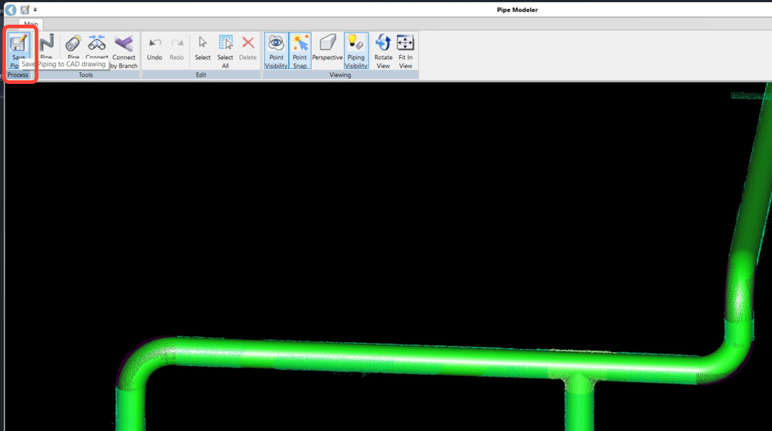
In the Process panel, click Save Piping to export the created pipe run into the CAD window. Then close Pipe Modeler.
-
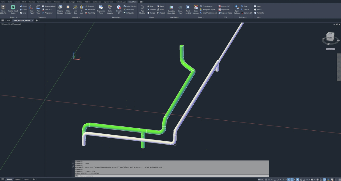
Review the result in the ModelSpace view:
-
Go to CloudWorx | Rendering and turn off point visibility.
-
Switch to the Visualize tab and set the view mode to Conceptual.
-
⬅️ Previous: Advanced Pipe Fitting in CloudWorx for AutoCAD