
This guide explains how to extract the geometry of complex pipe runs and use various connection types to join pipe segments correctly. It details advanced pipe-fitting techniques, such as using eccentric reducers and T-branch connections, to ensure accurate pipe geometry in the plant model.
Prerequisite: For full workflow context and results, review the preceding guides in this series:
Practice Data
Exercise CAD file (.dwg format)
Isolating Pipes to Extract
Pipe Object Classification
To simplify the identification of piping in the point cloud, let’s use the Classification feature.
1. Orient the point cloud to the Front view.
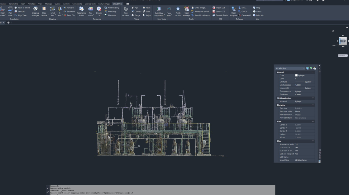
2. Navigate to Rendering and select Color Mapping.
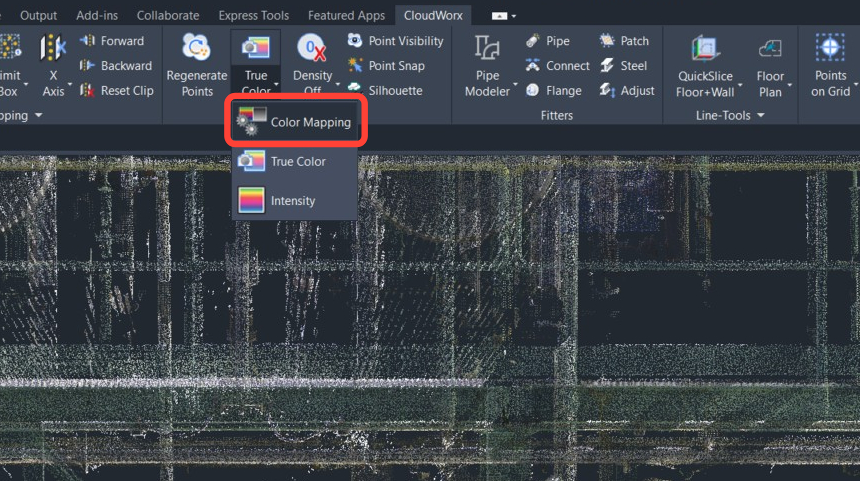
-
In the Point Cloud Color Mapping dialog, set Global Color Mapping to Classification and click Apply.
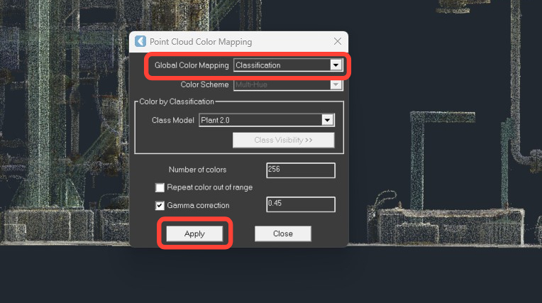
-
Click Class Visibility to see the classification table. Keep all classes selected for the next steps.
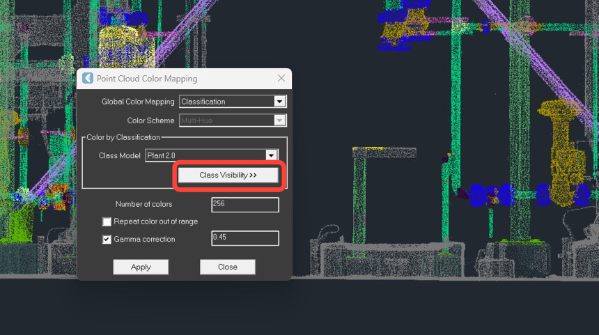
The piping now appears highlighted in green within the point cloud.
Clipping the Area of Interest
Clip out the area shown in the image below:
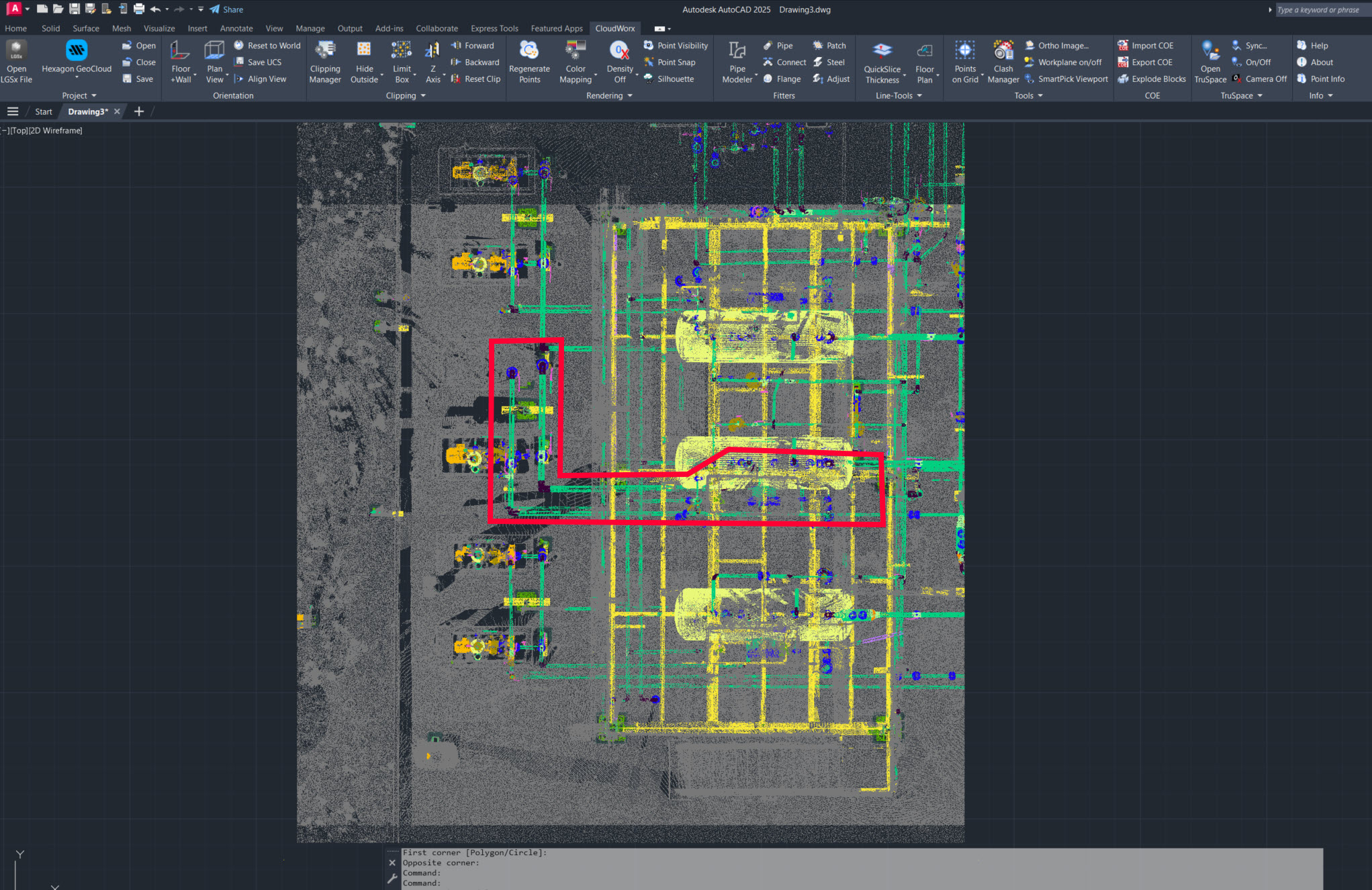
-
Use the View Cube to rotate to the Left view, then Navigate to Clipping | Hide Outside or type CWHIDEOUT in the command line.
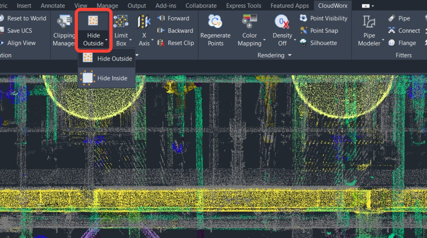
-
In the command line, select Polygon ot type P. Then draw a polygonal fence around the area of interest. Press Enter to finish drawing.
-
Use the View Cube to review the isolated section of the point cloud created for pipe extraction.
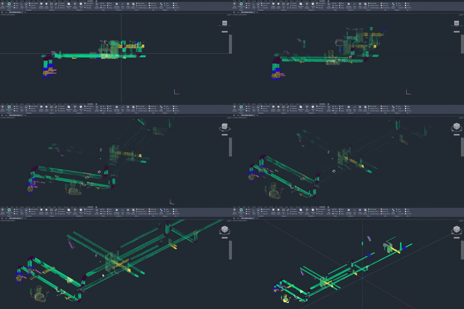
Extracting Pipe Geometry
Creating Straight Pipe Segments
-
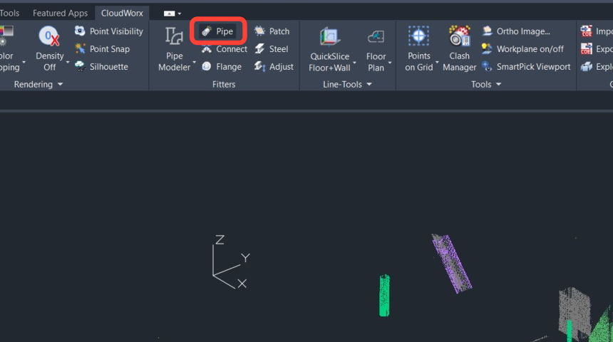
Enable the Pipe fitter. Go to Fitters | Pipe.
-
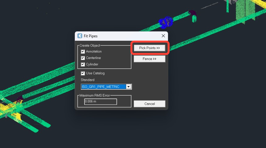
Configure the Pipe fitter as follows:
-
Ensure the Annotation, Centerline, and Cylinder check boxes are selected.
-
Select the Use Catalog check box and then select the required catalog. In this example, it’s ISO_GR1_PIPE_METRIC.
-
Click Pick Points.
-
-
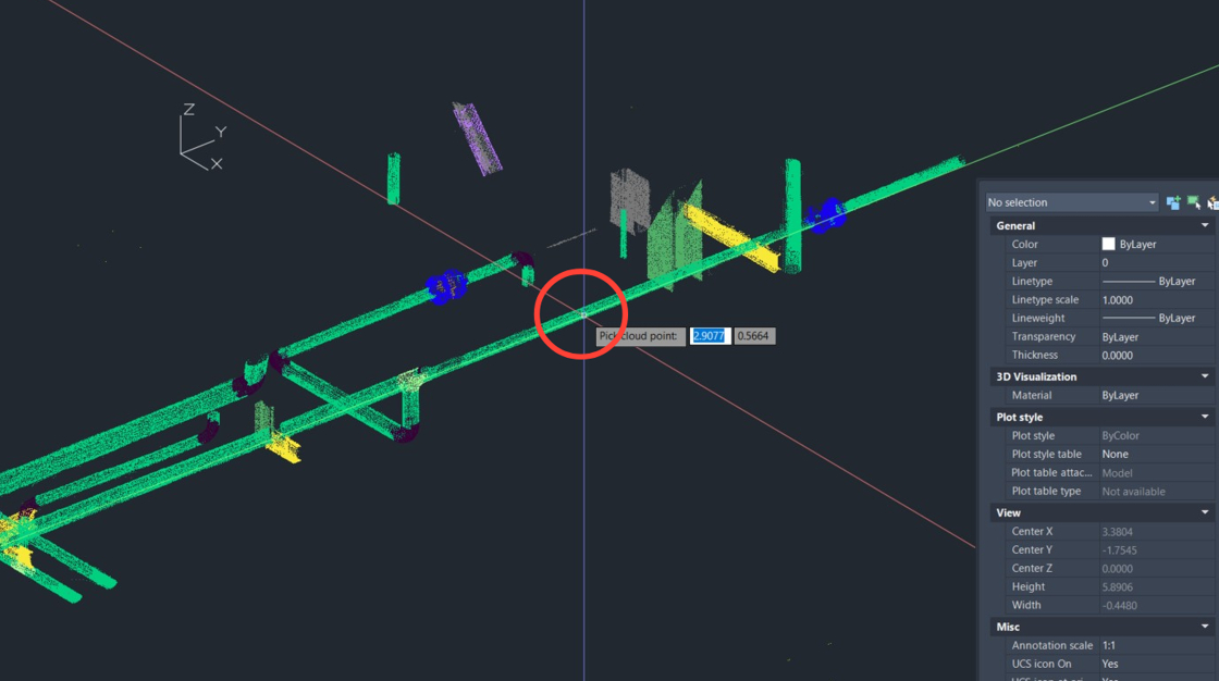
Pick a point on a straight segment of the pipe.
-
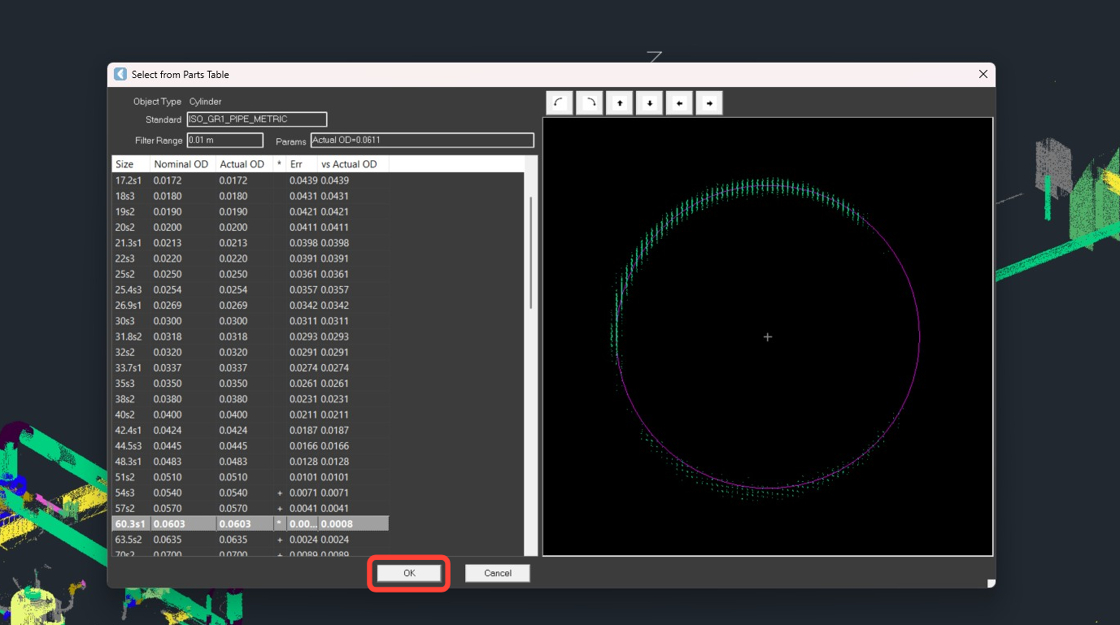
When the pipe is fitted, the results will appear in the Parts Table. Review the fit, make any needed adjustments, and then click OK.
-
Continue extracting straight pipe sections along the pipe run.
-
Review the extracted pipe geometry.
Tip: Turn off point visibility (Rendering | Point Visibility) to improve visualisation of results.
.jpeg?cb=3ec9ec1dbcaf9b373659ec6db9967db1)
Note: The Annotation option, enabled during Pipe fitter configuration, adds a tag to the centerline feature that shows the pipe diameter. This makes it easier to add compatible features, check pipe specifications, and label final drawings.
Connecting Pipes with Elbows
Now, let’s connect the extracted straight segments of the pipe run with elbows.
-
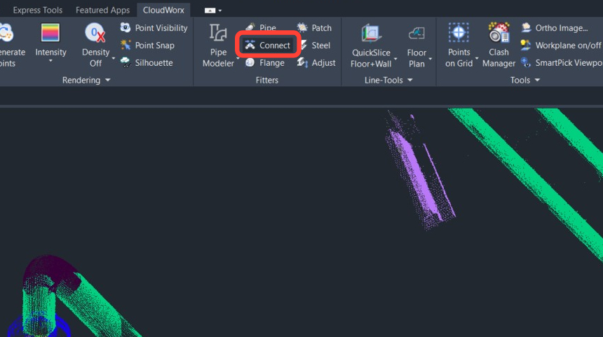
Go to Fitters and click Connect.
-
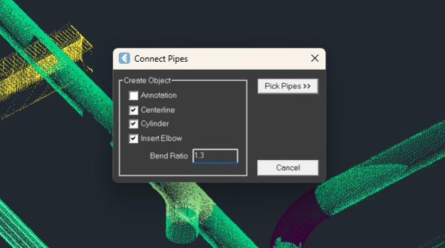
Configure the fitter as follows:
-
Ensure the Centerline, Cylinder, and Insert Elbow check boxes are selected.
-
Set Bend Ratio to 1.3.
-
-
Click Pick Pipes.
-
Turn off the point visibility.
-
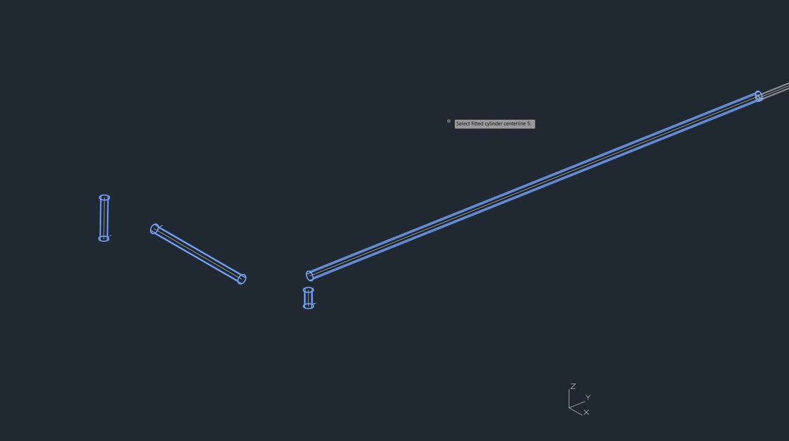
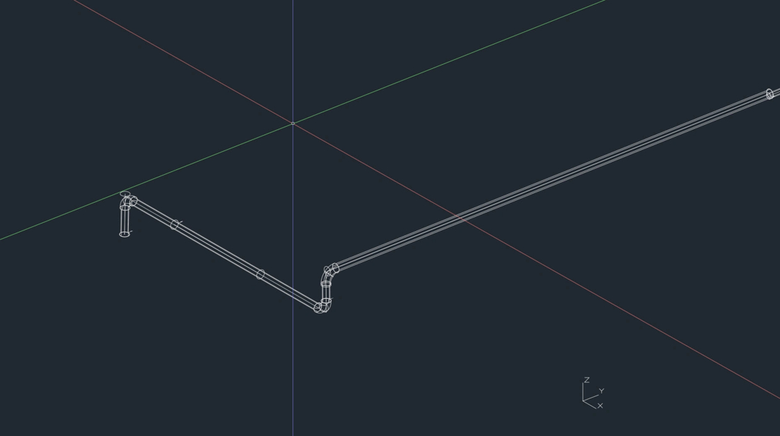
Select all pipe segments that should be connected with elbows and press Enter. The pipes will be connected automatically.
-
Turn on the point visibility.
Note: When creating connections where the connection seed pipe does not fit, CloudWorx does not automatically delete the old features and will instead creates new ones. The previous centerline object also remain in the drawing.
See image below:
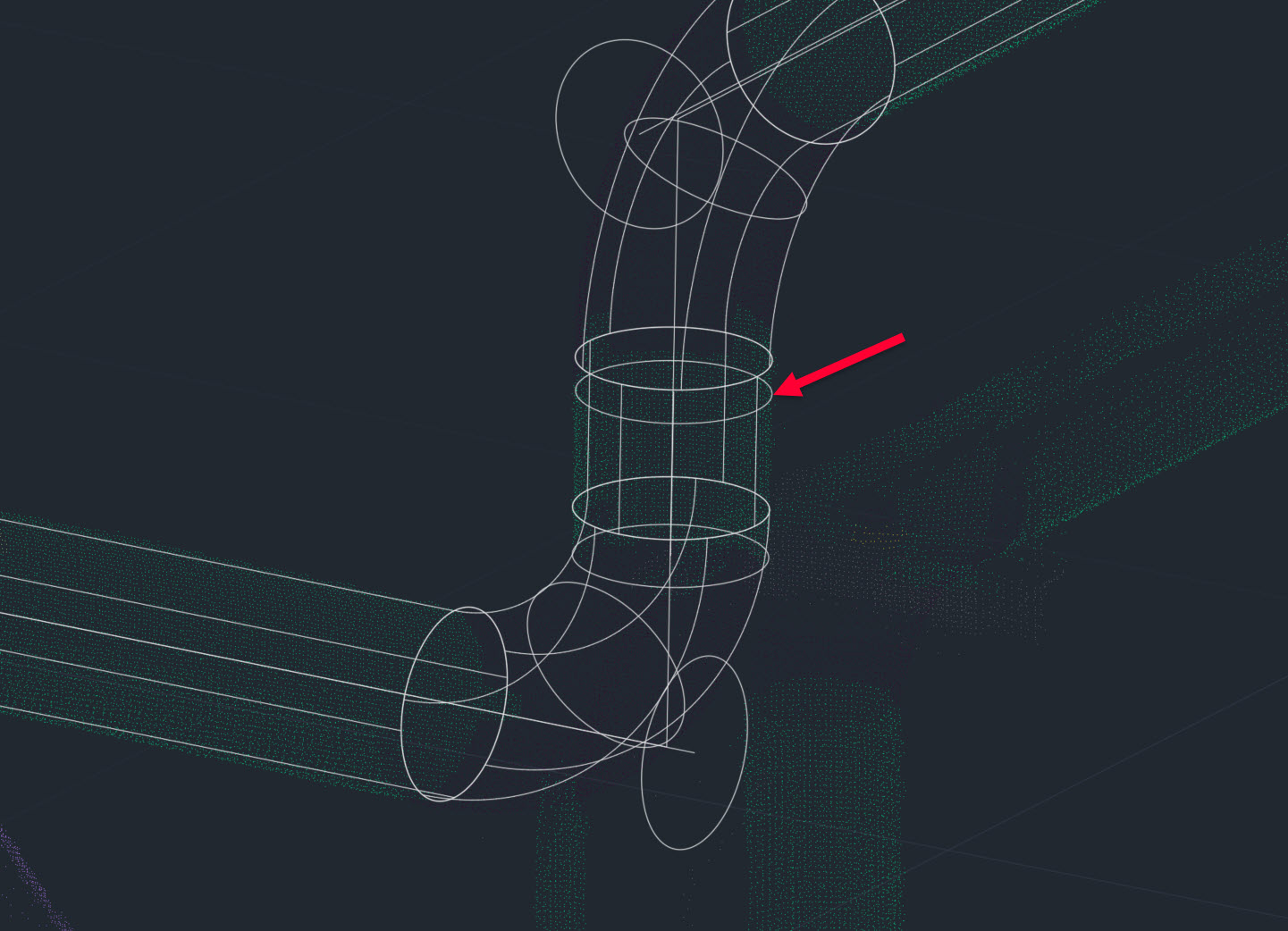
The old features will have to be manually deleted. One strategy to help is to put the initial pipes on another layer before connecting them on the current layer.
Adding Pipe Reducer
This part of the workflow shows you how to add a pipe reducer to connect pipe segments with different diameters.
-
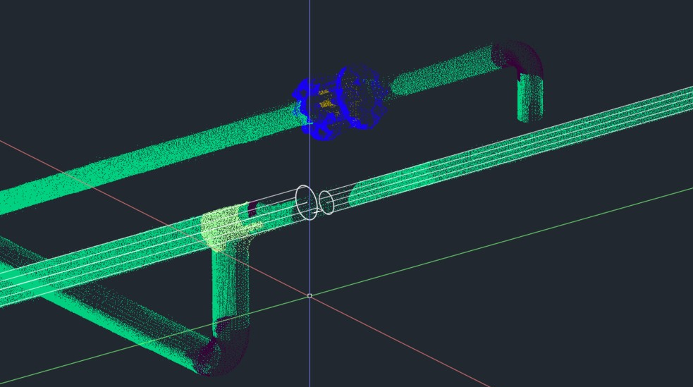
Adjust the point cloud orientation and zoom in on the area where the pipe diameter changes.
-
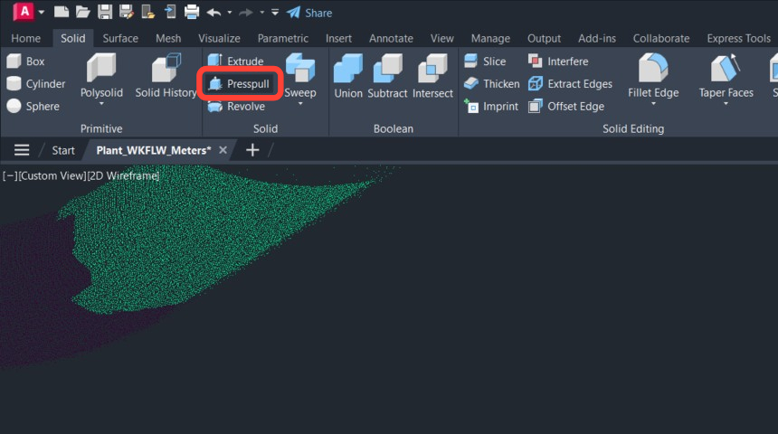
Go to the Solid tab and click Presspull.
-
Move the pipe geometry away from the intended reducer location.
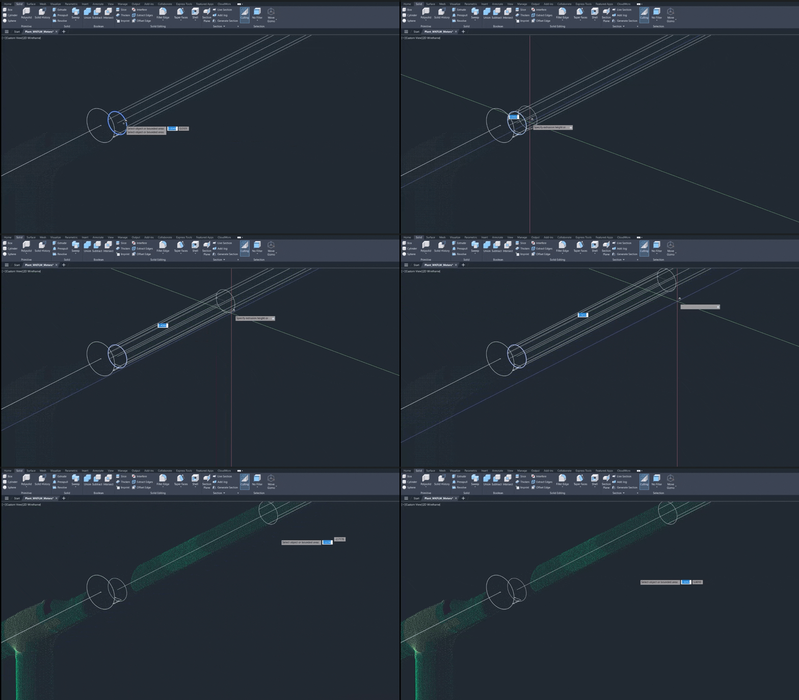
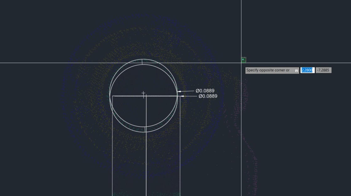
a. Now the pipe geometry is represented by a line and two circles at each end of the pipe segment.
-
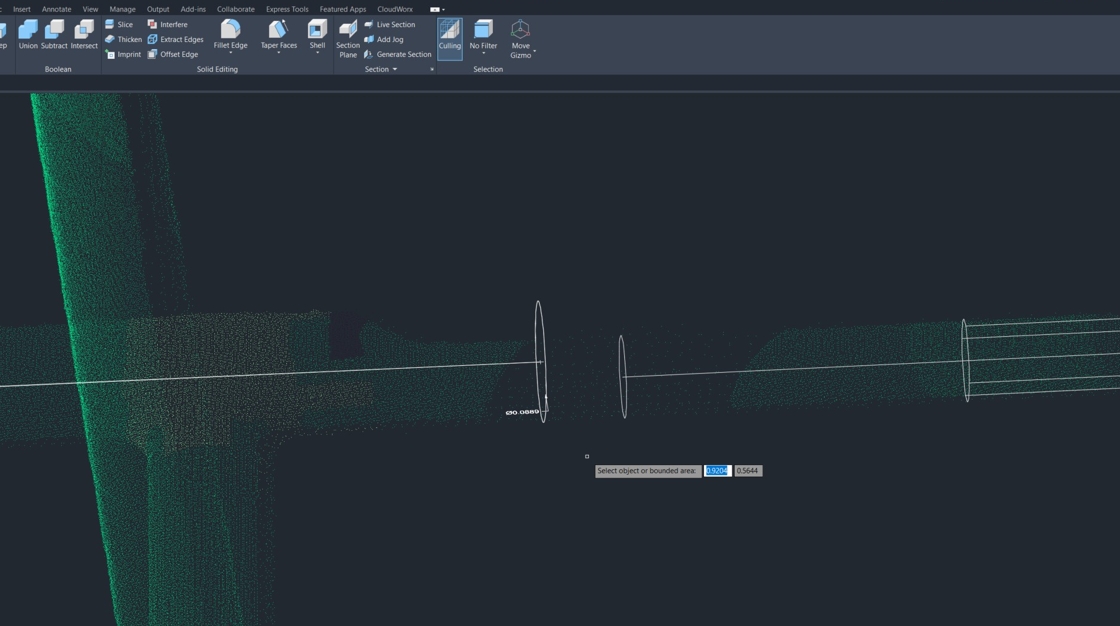
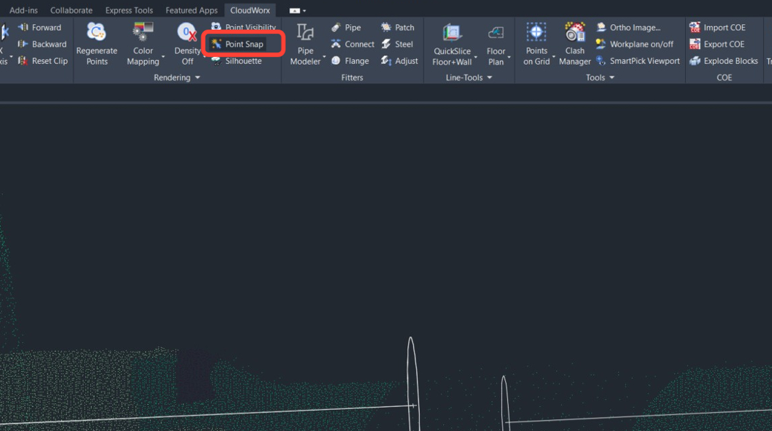
Turn off point snapping to ensure more precise control.
-
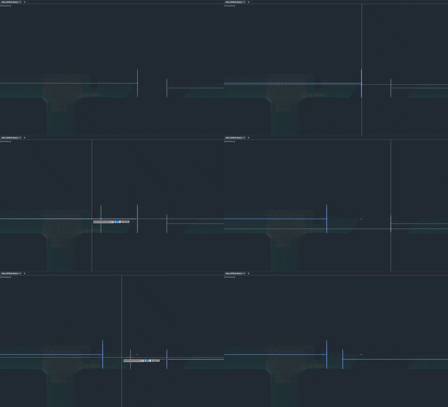
Zoom in on the pipe connection and adjust the centerline geometry to fit the point cloud at the point of the reducer connection.
-
Select both pipes, type the EXPLODE command, and press Enter.
-
The circles intended to form the reducer are now ungrouped.
-
.jpeg?cb=eb55bd23aa16e68e46a305fabc040c4d)
-
To model a pipe reducer, activate the LOFT command.
-
Go to the Solid tab and select Loft, or type LOFT in the command line.
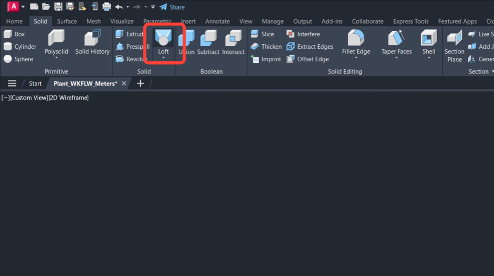
-
Select the two circles that represent the cross-sections of the reducer and press Enter.
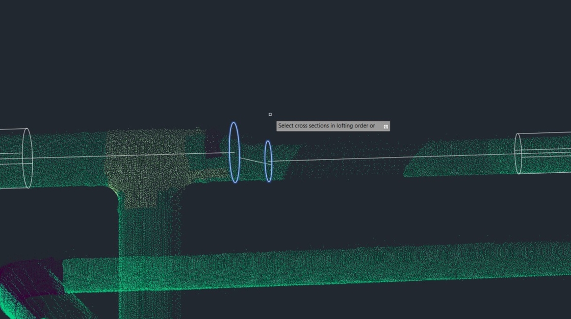
-
Select Cross sections only among the suggested options.
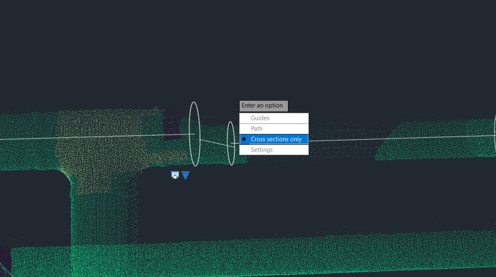
-
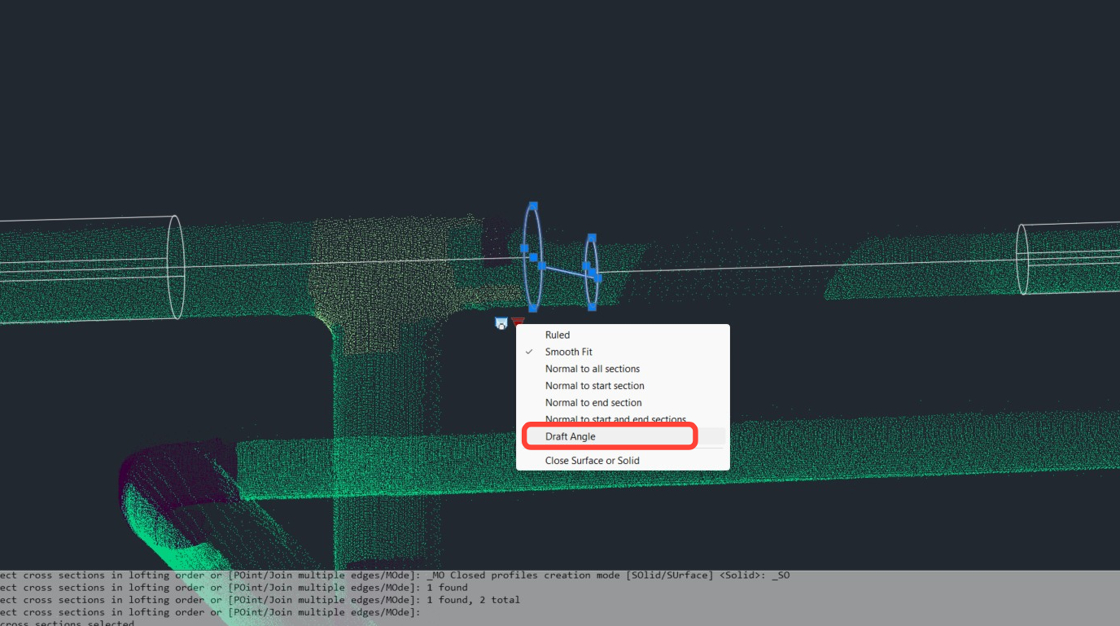
Select the reducer geometry and click the direction arrow below.
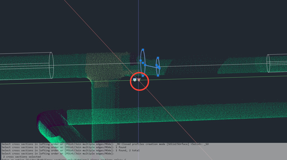
-
Select Draft Angle among the suggested options.
-
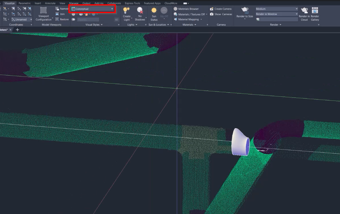
Adjust the visual style of the reducer to review the result.
-
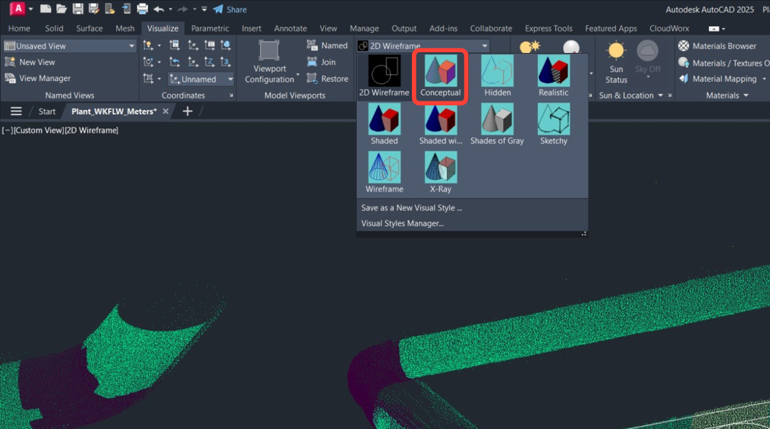
Go to the Visualize tab and select the Conceptual visual style.
-
-
Use the PRESSPULL command to adjust the length of the pipe segments so they match the reducer.
-
Click Solid | Presspull.
-
Select each pipe segment and drag it to connect with the reducer.
-
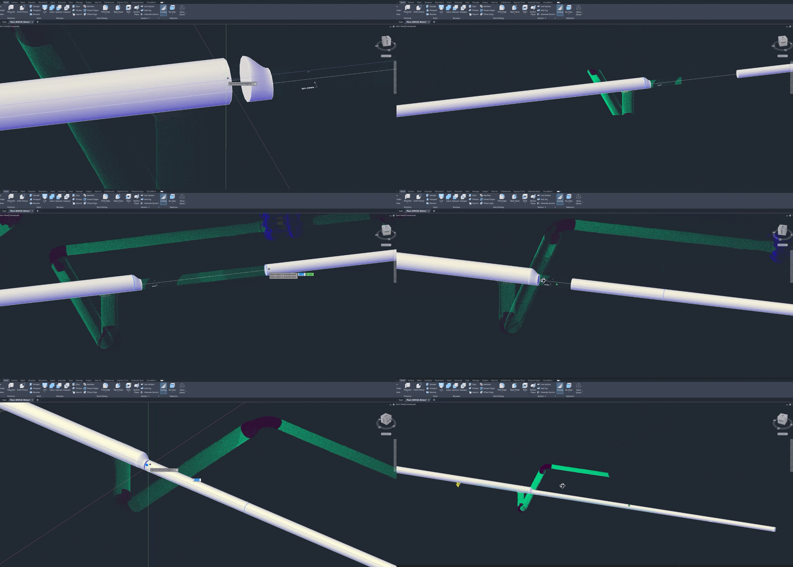
The pipe segments with different diameters are now joined using the eccentric reducer.
Adding T-Branch Connection
Now, let’s connect segments of the T-shaped pipe.
-
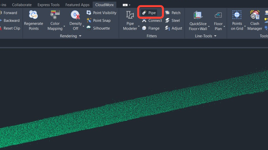
Navigate to CloudWorx and enable the Pipe fitter.
-
In the Fit Pipes dialog, do the following:
-
Select the Centerline and Cylinder check boxes.
-
Select the Use Catalog check box and select the required catalog. In this example, it’s ISO_GR1_PIPE_METRIC.
-
Click Fence.
-
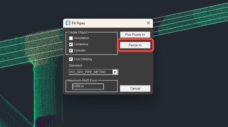
-
Draw a fence around the pipe segment to extract.
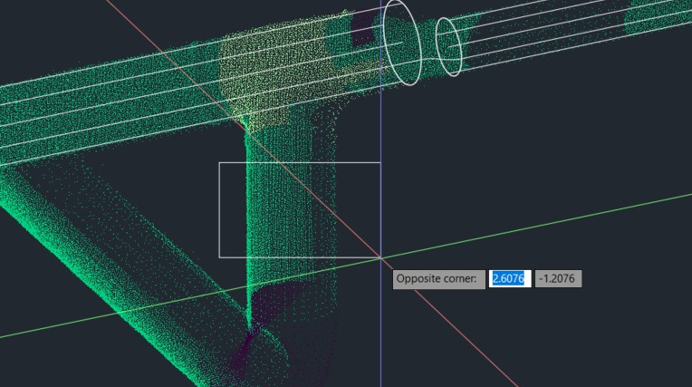
-
Verify the suggested catalog fit, make any necessary adjustments, and click OK.
-
The pipe segment will be created.
-
.jpeg?cb=46ab1a48f7b46cd32b26f8ed546547aa)
-
Go to Fitters and click Connect.
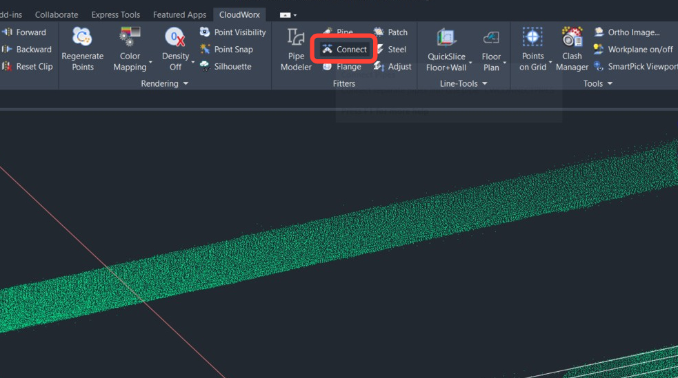
-
In the Connect Pipes dialog, deselect the Insert Elbow check box so no elbow is created, and click Pick Pipes.
.jpeg?cb=43ba03b11cb45ed58d4565cea851bf1d)
-
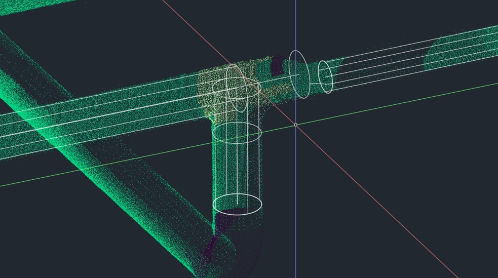
Select both pipe segments and press Enter to join them.
-
CloudWorx will automatically reroute the centerline to the new connection. Now, the primary pipe should be readjusted to the reducer using the PRESSPULL command.
-
On the Solid tab, click Presspull.
-
Click the end of the pipe to be adjusted and drag it to the reducer.
-
The pipe is adjusted correctly, and the T-branch is created.
-
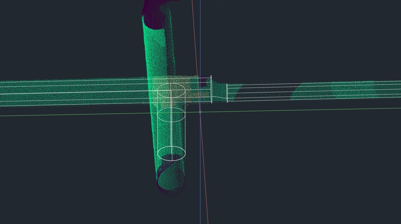
-
On the Visualize tab, adjust the visual style to Conceptual to view the created geometry.
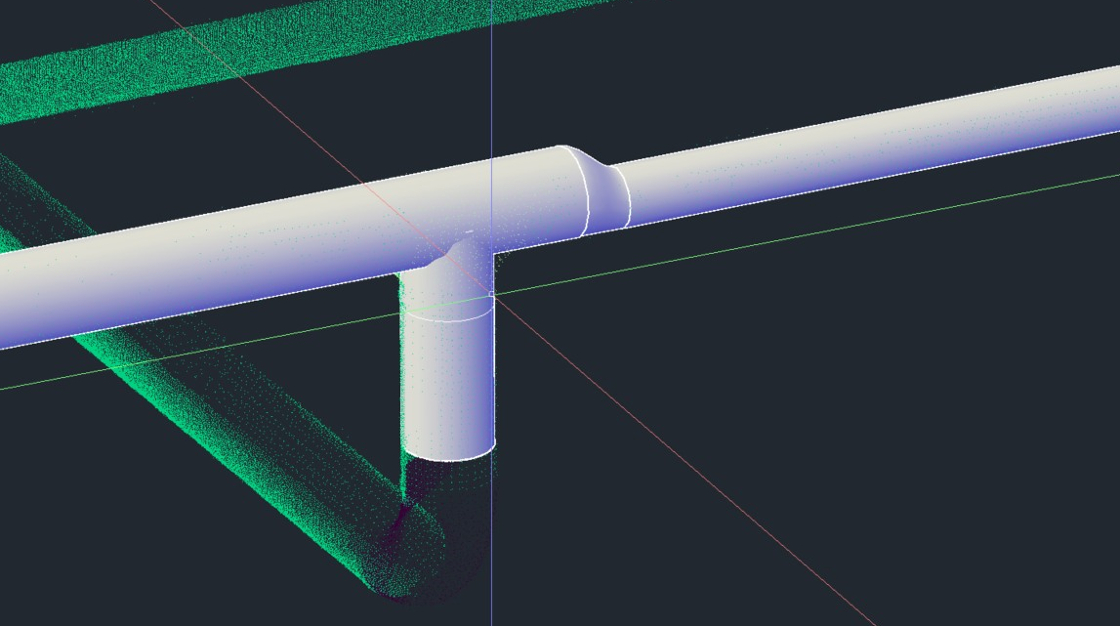
As a result, you can inspect the pipe run with segments joined by a T-branch connection and an eccentric reducer.
⬅️ Previous: Advanced Steel Fitting in CloudWorx for AutoCAD