This guide provides a comprehensive overview of using the TruSpace tool in CloudWorx for AutoCAD to create native CAD objects and specific CloudWorx-based objects as detailed in the workflow below.
Practice data
Initial Steps
-
Before exploring the topic, create a new project and import a dataset using an appropriate import option. Refer to the Connect To Help section for more details.
In this workflow, a dataset is saved as the LGSx file, which is then imported as follows:
1.1. In the Project panel, click Open LGS File and browse to the required file.
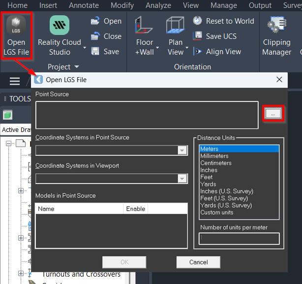
1.2. If the imported point cloud does not appear in the CAD window, zoom to the extents using any option below:
▪️ Enter the command line prompt: Z | E.
▪️ Double-click the mouse wheel.
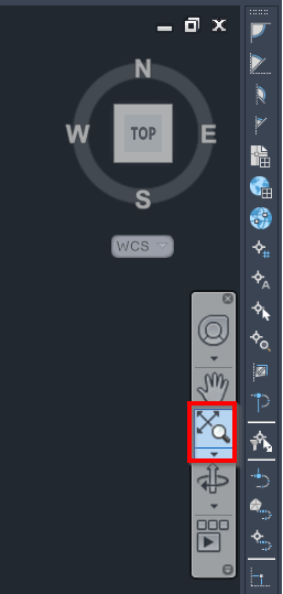
▪️ Click Zoom Extents in the toolbar located on the right-hand side of the CAD window.
It may happen when a point cloud is imported with a custom UCS, which can prevent it from aligning correctly since the new drawing's origin is set to 0,0,0.
Navigating in TruSpace
TruSpace enables quick and easy 3D viewing of point cloud data, synchronising seamlessly with the main CAD window. It makes it easy to select a cloud point from which the feature of interest is visible to create CAD objects using regular CAD commands.
-
In the TruSpace panel, click Open TruSpace.
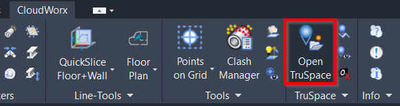
-
Pick any cloud point in the CAD window, and the TruSpace viewer will open in a new window.
Note: Ensure the following features are enabled:
-
CloudWorx point snapping (refer to the PointSnap Help page)
-
AutoCAD node snapping (Drafting Settings | 3D Object Snap | Node)
-
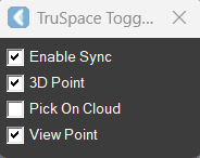
In the TruSpace Toggles dialog, select the synchronisation settings to ensure successful use of TruSpace:
-
Enable Sync: Enable to ensure viewpoint synchronisation with the TruSpace viewer.
-
3D Point: When enabled, CloudWorx submits a 3D pick from the TruSpace viewer to the CAD command line. This pick can be used by CAD commands that accept 3D coordinates.
-
Pick On Cloud: When enabled, CloudWorx recomputes the pick made in the TruSpace viewer based on the closest cloud points visible in the CAD window. Recomputation may fail if there are not enough points near the pick or when the points are clipped or hidden in CloudWorx.
-
View Point: When enabled, the viewpoint of the active CAD viewport automatically updates to match the TruSpace viewpoint.
Once the necessary synchronisation settings are enabled, you can navigate confidently in TruSpace, and the view will be automatically synchronised in the CAD window.
Note: To rotate the view, hold the left mouse button while spinning in the desired direction. Use the wheel to zoom in or out.
Tip: To get a better view of the scanned data in TruSpace, you can turn off the point cloud visibility in the Visibility panel. This enables you to examine the data as panoramic images, which can assist in preparing accurate linework.
Creating Native CAD Objects
Using TruSpace is beneficial for achieving a more realistic representation of CAD objects. It enables accurate selection of cloud points and allows for easy tracing of the lines that represent the object. This is especially useful if you want to avoid complicated clipping or if you simply need to outline a specific object while still being able to view the entire point cloud.
-
In the CAD window, enter the command line prompt to draw the desired CAD object.
In this workflow, we will create 3D polylines, representing a wall and a bracing column using the 3DPOLY CAD command.
-
Switch to the TruSpace viewer and pick points in the sequence that you want the line to follow:
Note: Although cloud points can still be picked in the CAD window, TruSpace enhances the accuracy of the selection process.
6.1. Specify the start point of the polyline.
6.2. Specify the endpoint of the polyline.
6.3. In the CAD command line, either type Enter to finish line editing or click Close polyline to finish line editing and disable the CAD command.
You will see the lines generated from the picks in the CAD window.
-
Review the created CAD geometry in a CAD window:
7.1. Close TruSpace.
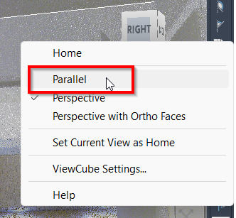
7.2. In the CAD window, right-click the view cube and change the viewing mode from Perspective to Parallel.
7.3. In the Rendering panel, turn off the point visibility to view the 3D CAD objects you created.
Creating CloudWorx-Based CAD Objects
TruSpace also provides valuable assistance in creating CAD objects using specific CloudWorx tools.
This part of the workflow demonstrates how to use TruSpace to fit pipes and structural steel sections, enhancing precision and efficiency during the linework process.
Creating Separate Pipes
-
Open TruSpace and zoom in on the pipe you want to create.
-
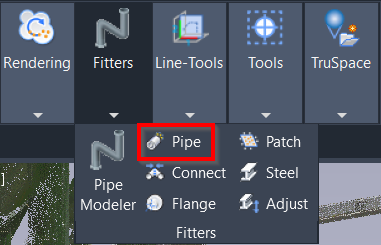
Switch to the CAD window, go to the CloudWorx tab and select the Pipe tool in the Fitters panel.
-
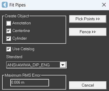
In the Fit Pipes dialog, take the following steps:
10.1. In the Create Object field, select check boxes for Centerline and Cylinder.
10.2. Select the Use Catalog check box and choose the necessary catalogue.
10.3. Click Pick Points and navigate to TruSpace to choose the points required for creating the pipe.
10.4. After selecting a point, choose the pipe type from the catalogue in the Select From Parts Table dialog, and the created pipe will appear in the CAD window.
Connecting Pipes
-
To connect several pipes into one, take the following steps:
11.1. Go to Rendering | Point Visibility and disable the point visibility to clearly see the created CAD objects.
11.2. Navigate to the Fitters panel and select the Connect Pipes tool.
11.3. In the Connect Pipes dialog, select the check boxes for Centerline, Cylinder, Insert Elbow. Then click Pick Points and select the pipes that should be connected with an elbow.
Note: After the connector is added, the original centerline and diameter objects are kept for future use.
11.4. To better visualise the created pipe, navigate to the View tab in your CAD system or enter the VISUALSTYLES command line prompt and select the appropriate visual style for the created pipe.
Creating Steel Structural Elements
-
Open TruSpace and zoom in on the steel structural elements you want to create.
-
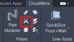
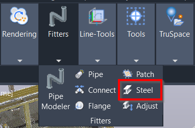
Switch to the CAD window, go to the CloudWorx tab and select the Steel tool in the Fitters panel.
-
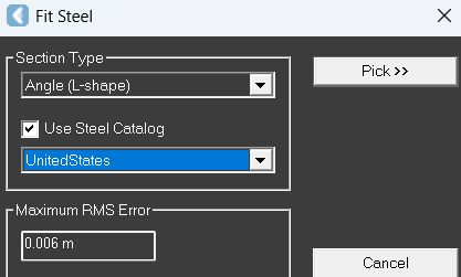
In the Fit Steel dialog, take the following steps:
14.1. In the Section Type field, select the type of the steel element.
14.2. Select the Use Steel Catalog check box and choose the necessary catalogue.
14.3. Click Pick, navigate to TruSpace and choose the start and end points for the steel element.
14.4. In the Select from Parts Table dialog that will appear, adjust the steel element as needed and click OK.
.png?cb=f494edf9e5b780f40c0b7f2e232457e7)
-
Review the result in the CAD window:
15.1. Switch back to the Parallel view (see Step 7.2).
15.2. In the Rendering panel, turn off the visibility of points.
Conclusion
TruSpace helps enhance the efficiency of working with point cloud data in a CAD environment. Its seamless synchronisation with the main CAD window allows for quick 3D navigation and easy selection of cloud points, simplifying the creation of CAD objects. By providing a realistic representation and eliminating complicated clipping operations, TruSpace facilitates more accurate design and streamlines the linework.