This guide provides a comprehensive overview of the Floor Plan tool, detailing the initial steps required to activate it and exploring its features through a sample workflow in AutoCAD.
Practice data
Initial Preparations
Adjusting Settings
-
Start a new drawing in AutoCAD.
-
To allow snapping to cloud points, ensure that AutoCAD’s Object Snap setting is enabled:
2.1. Navigate to the Object Snap Settings from the toolbar available in the lower-right corner of the CAD window.
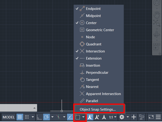
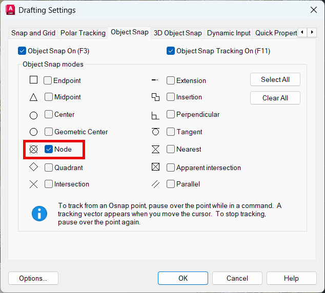
2.2. In the Drafting Settings dialog, go to the Object Snap tab and ensure Node is selected in the Point Cloud settings. It is the minimum required to select objects in the point cloud.
Importing Project Data
-
Import the project data.
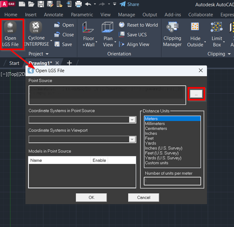
Note: In this workflow, BLK360 data is saved as the LGSx file. If your data is stored in a different format, please choose the appropriate import option. Refer to Connect To Help section for more details.
3.1. In the Project panel, click Open LGS File and browse to the required file.
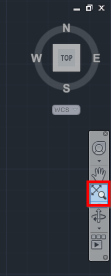
3.2. If the imported point cloud isn't visible in the CAD window, click Zoom Extents in the toolbar available on the right-hand side of the CAD window.
This may occur because, in a new drawing, the origin is set to 0,0, while the imported point clouds may have a different origin, such as a projected coordinate system or a custom UCS.
Orienting Point Cloud
Establishing a user coordinate system (UCS) is a helpful practice for properly aligning and orienting features in a drawing. It facilitates the drafting process and ensures that the final drawing is oriented in a way that is easier to view and annotate. See Orientation for more details.
-
Create a UCS to orient a point cloud to the X and Y axes of the AutoCAD window.
4.1. Go to the Orientation panel and select the UCS orientation method. In this example, the 2 Points method is described.
4.2. Select 2 points on the point cloud to align the UCS axes to the building. The first pick point defines the origin of the new UCS, and the second pick point defines the direction of the X-axis; the direction of the Z-axis (up direction) is not changed.
4.3. If necessary, use the ViewCube to fine-tune the orientation.
Creating Quick Slice
To speed up processing of point cloud data, it can be helpful to temporarily hide unnecessary points. By eliminating specific portions of data, you can focus on the area of interest and avoid unintentionally selecting points outside of it. Additionally, setting up a quick slice is essential before utilizing the polyline tools available in the Floor Plan tool. See QuickSlice for more details.
Note: If you keep the point snap setting turned on, you will be snapping to the cloud points. So, when creating a quick slice, it's easier to temporarily turn off point snapping. This way, you won't snap to any points and can clip out the area you want regardless of point density and availability.
-
Create a quick slice using any of the options below:
5.1. Option A: Using the ViewCube, switch to the TOP view and type CWQSLICE | U in the command line to create a quick slice from the current UCS.
Note: The created quick slice can be viewed in the Clipping Manager (Clipping | Clipping Manager) from where you can activate, deactivate, or delete it.
5.2. Option B: Using the ViewCube, switch to the FRONT view and navigate to Line-Tools | QuickSlice Wall to create a quick slice on the wall. If the patch fitting is failed, simply select another point on the wall.
-
If you want to change the slice thickness, navigate to Line-Tools | QuickSlice Thickness or enter CWQSLICE | T in the command line and then type the required value for the slice thickness. The default thickness is 5 meters.
In some cases, it may be helpful to change thickness to create a thinner slice, which can enhance the clarity of the lines. Additionally, if the wall is tilted, adjusting the thickness can make the center of the wall less ambiguous.

Note: The slice thickness can also be adjusted in the Floor Plan tool using a slider (see Step 9).
-
(Optional) To achieve higher contrast with the background and improve point visibility, you may change the color mapping as follows:
7.1. On the Rendering tab, click Color Mapping.
7.2. In the Point Cloud Color Mapping dialog, select Appearance from the Global Color Mapping drop-down list.
7.3. Select the desired color and click Apply.
Using Floor Plan Tool
-
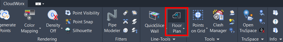
Go to Line-Tools and click Floor Plan. The Floor Plan tool will open in a separate window.
-
Adjust the thickness and position of the slice along the Z-axis by using the slider on the left.
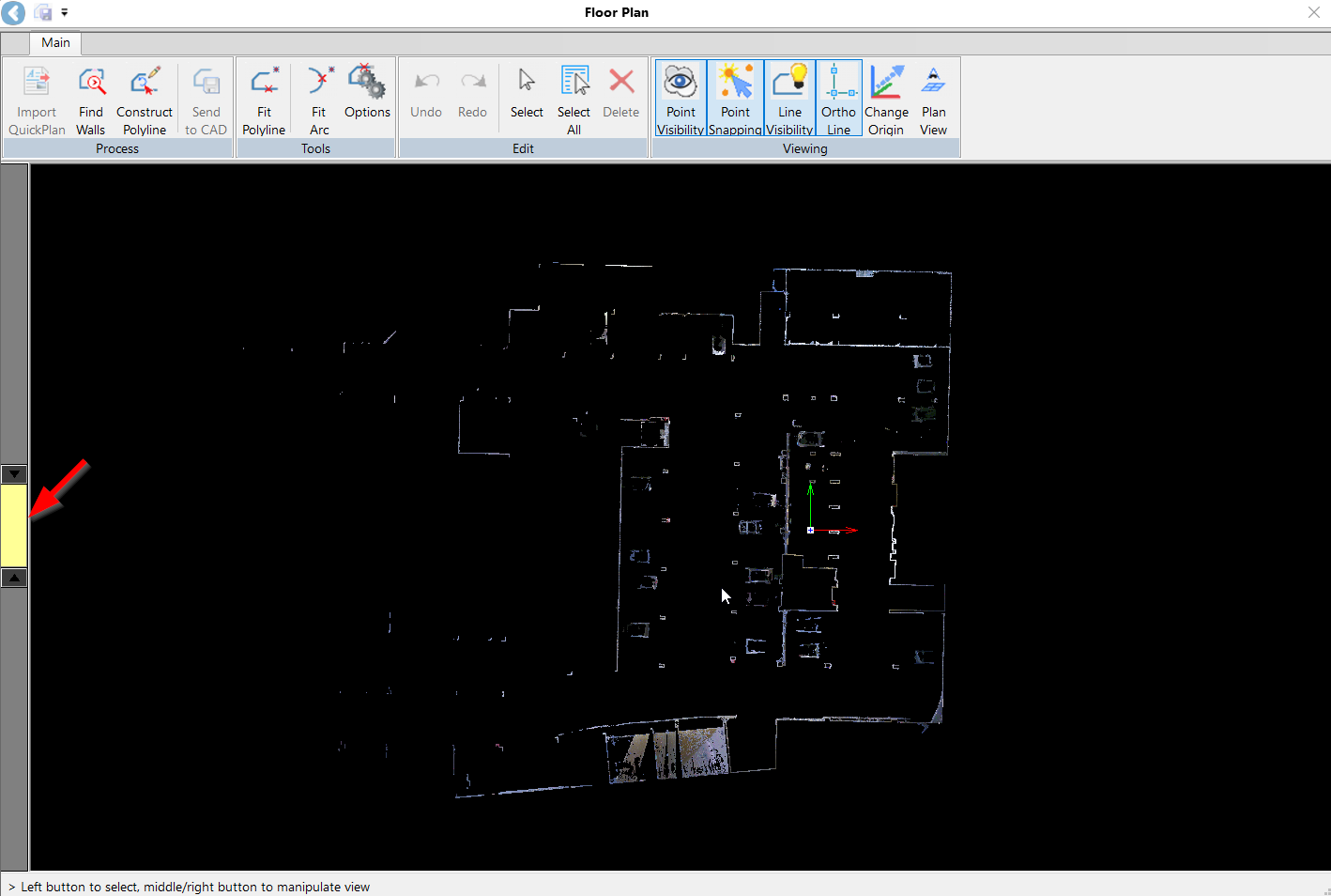
Tip: For better navigation within the selected tools, refer to the hints displayed in the lower-left corner of the Floor Plan tool.
Creating Preliminary Floor Plan (Automatic)
-
There are two methods of automatically generating a preliminary floor plan:
10.1. Import Quick Plan.
Click Import QuickPlan in the Process panel to import a QuickPlan DXF file created in Cyclone FIELD 360. The imported lines can then be edited and adjusted to create a floor plan.
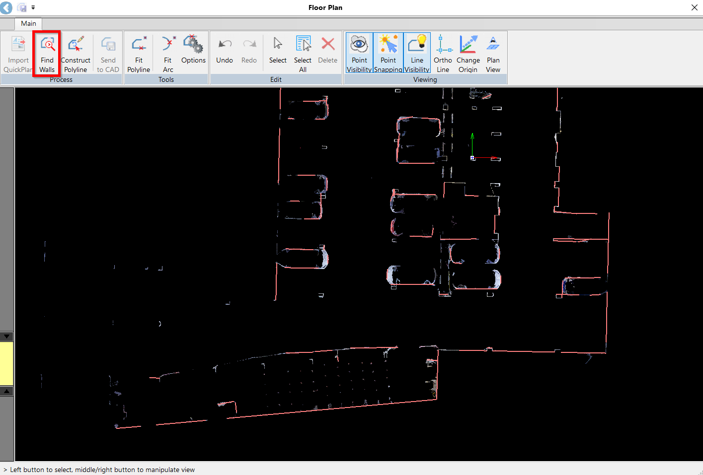
10.2. Find Walls
If QuickPlan is unavailable, in the Process panel, click Find Walls to automatically extract wall lines. The Floor Plan tool will identify all possible line segments and display them as red lines.
-
Verify the suggested line segments and connect them in a polyline. The Floor Plan Tool offers a combination of Automated, Semi-Automated, and Manual options for completing a drawing.
11.1. Automatic
In the Process panel, click the Construct Polyline tool to enable line drawing. If you are satisfied with the suggested line, click on it, and it will turn yellow, indicating that it has been verified and approved. Repeat this step for other properly extracted line segments.
11.2. Semi-Automatic
If you need to adjust the angle of two line segments, enable the Ortho line tool in the Viewing panel. Simply select the line you want to adjust and the tool will try to adjust the selected line as close to the angle as possible.
11.3. Manual
In areas with complex wall structures where the line is partially detected, you can draw the line manually. Click on the line at the starting point, drag it in the desired direction, and release the mouse at the endpoint. The tool will attempt to draw line segments along the path you have traced.
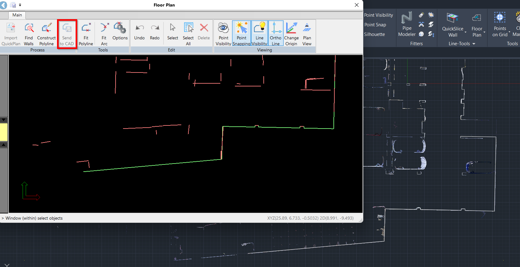
11.4. Once the polyline is created, click End Polyline in the Construct Polyline panel to exit the tool. The created polyline will become green.
11.5. To connect unconnected lines, select both lines so that they appear purple. Then, drag the endpoint of the line you want to move to the destination endpoint on the other line. When the two endpoints are close to each other, the moving endpoint will snap to the fixed one.
-
Fine-tune the linework and make final adjustments:
12.1. If you see any mismatching between the created polyline and point cloud data, select the vertex of the lines that should be adjusted and drag it to align with the point cloud. The selected lines will turn violet, indicating they are editable.
12.2. Once you are happy with the result, click the Send to CAD button in the Process panel. The green (approved) line will disappear from the Floor Plan tool and appear as a solid white line in the CAD window.
Tip: For optimal results, position the Floor Plan tool and your CAD window on separate screens. This will allow you to verify the linework immediately as it is sent from the Floor Plan tool to CAD.
Refining Floor Plan (Semi-Automatic)
After making full use of the automatic preliminary Floor Plan tools, you may wish to refine the Floor Plan further by extracting additional polylines.
Fitting Polylines
-
Sometimes, low point cloud density will make automatic line extraction difficult. In this case, use the Fit Polyline tool in the Tools panel to create lines in areas where the lines haven’t been extracted automatically:
13.1. Click on each line representing a structure that needs to be drawn. The lines will be generated and highlighted in yellow.
13.2. Click Close Polyline to complete the drawing of a polyline. After the polyline is closed, all lines forming a structure will turn green.
13.3. Adjust the lines to ensure they fit the structure properly. Refer to Step 10.1.
13.4. Click Send to CAD in the Process panel to save the polyline.
Fitting Arcs
-
To draw structures with rounded edges—for example, columns, staircases, and so on—use the Fit Arc tool in the Tools panel:
14.1. Specify the starting point and endpoint of the arc. The arc will be created.
14.2. To adjust the arc, click the polyline again and make the necessary adjustments.
Tip: When data noise results in an unclear line, disable point visibility to refine the finish line more effectively. The Floor Plan tool simplifies the process of adjusting the fit of a finished line, even under less than ideal conditions.
14.3. Click Send to CAD to save the created arc on the CAD drawing.
Reviewing Created Floor Plan
-
After completing your work in the Floor Plan tool, close it.
Only approved lines will be saved. Any remaining red line segments will be discarded and ignored.
-
In AutoCAD, disable point visibility to clearly view the generated floor plan.