This guide explains how to use manual and automatic fitting tools to extract the geometry of steel structural elements, including beams, columns, crossbraces, and similar elements.
Prerequisite:
Before proceeding, complete the Advanced Workflow for Using Line Tools Guided Workflow to perform project setup and extract concrete footing outlines of the provided plant model.
Practice Data
Exercise CAD file (.dwg format)
Creating Steel Beams Based on Catalog
Clipping the Area of Interest
-
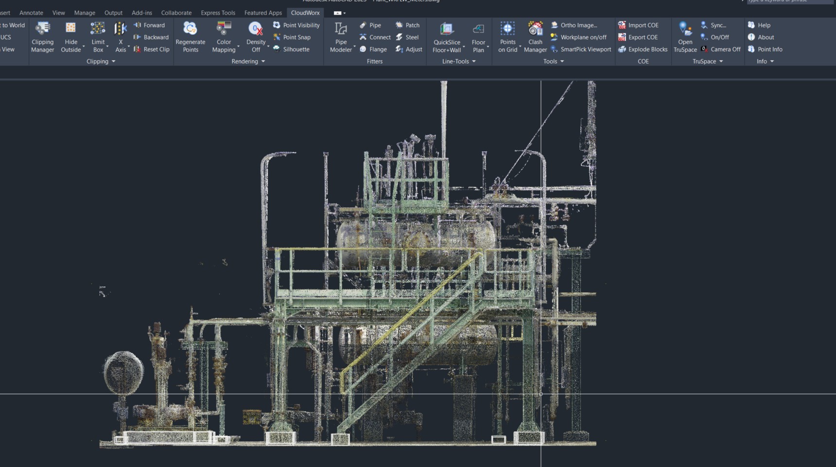
Orient the point cloud to display a profile view.
-
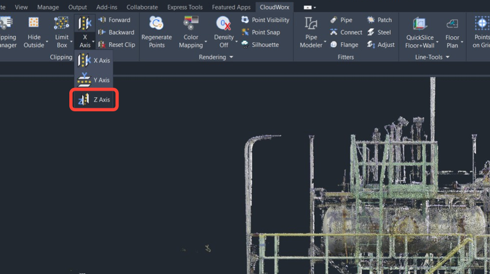
Navigate to Clipping and select Z Axis for slice creation.
-
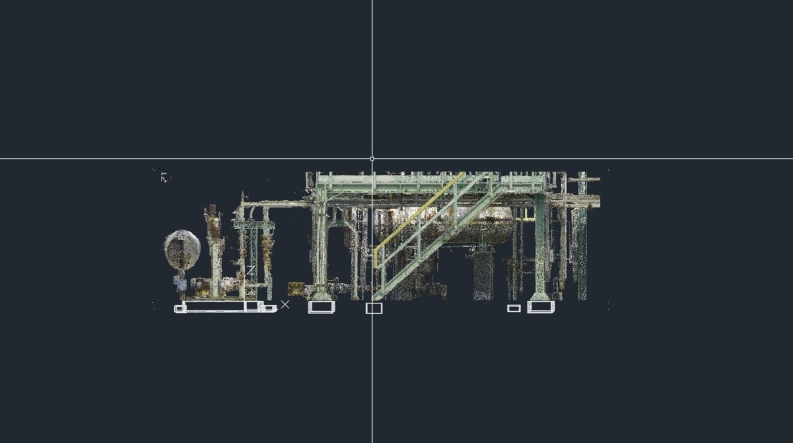
Select two clip panes to create a slice. The slice should clip out the ground, footings, and features above the platform, as shown in the image below.
Steel Object Classification
-
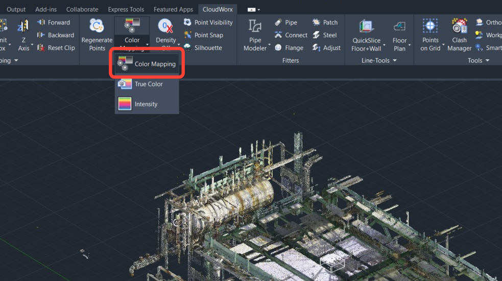
Navigate to Rendering and select Color Mapping.
-
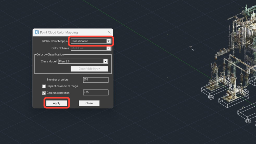
In the Point Cloud Color Mapping dialog, set Global Color Mapping to Classification and click Apply.
-
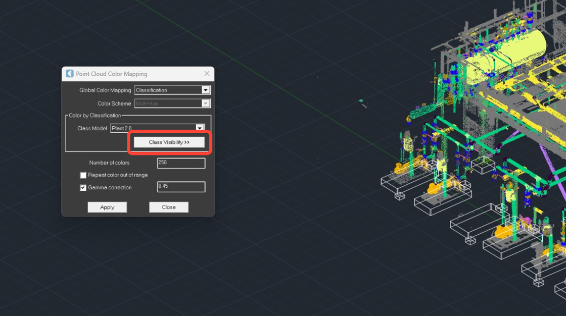
Click Class Visibility to show the classification table.
-
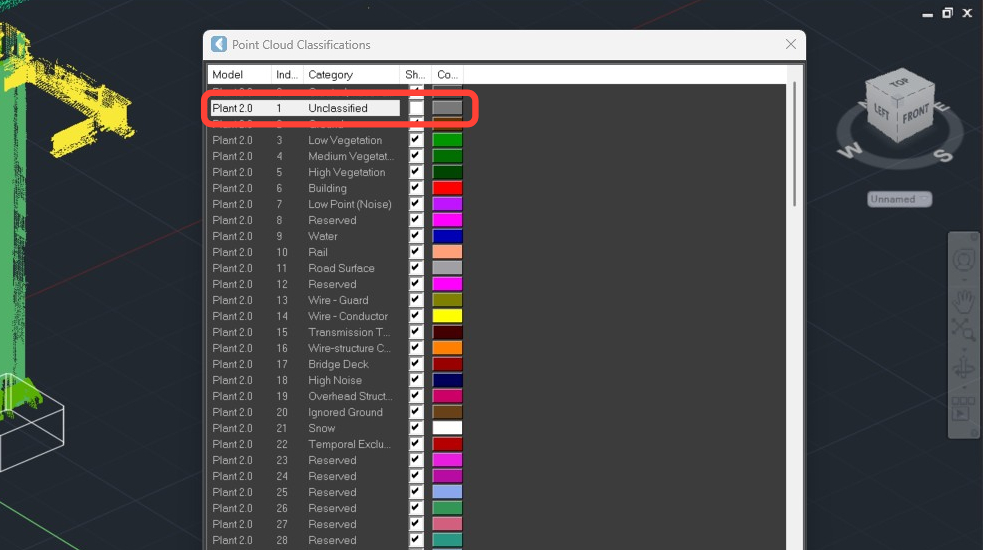
Deselect the Unclassified check box to hide unclassified points. This will display only relevant points classified by the plant model, which includes steel and pipe objects.
Extracting Steel Geometry
-
Enable the Steel fitter. Go to Fitters | Steel.
.jpeg?cb=6869d0f3d53caf5ea3f90c89bc401234)
-
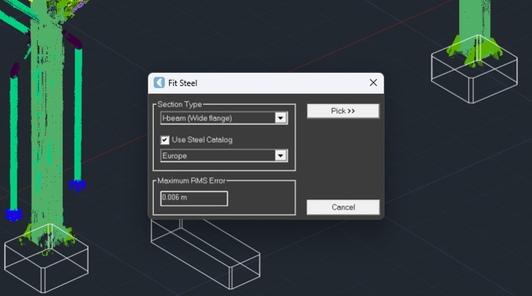
Configure the Steel fitter as follows:
-
Set Section Type to I-beam (Wide flange).
-
Select the Use Steel Catalog check box and then select the required catalog.
-
Then click Pick.
-
-
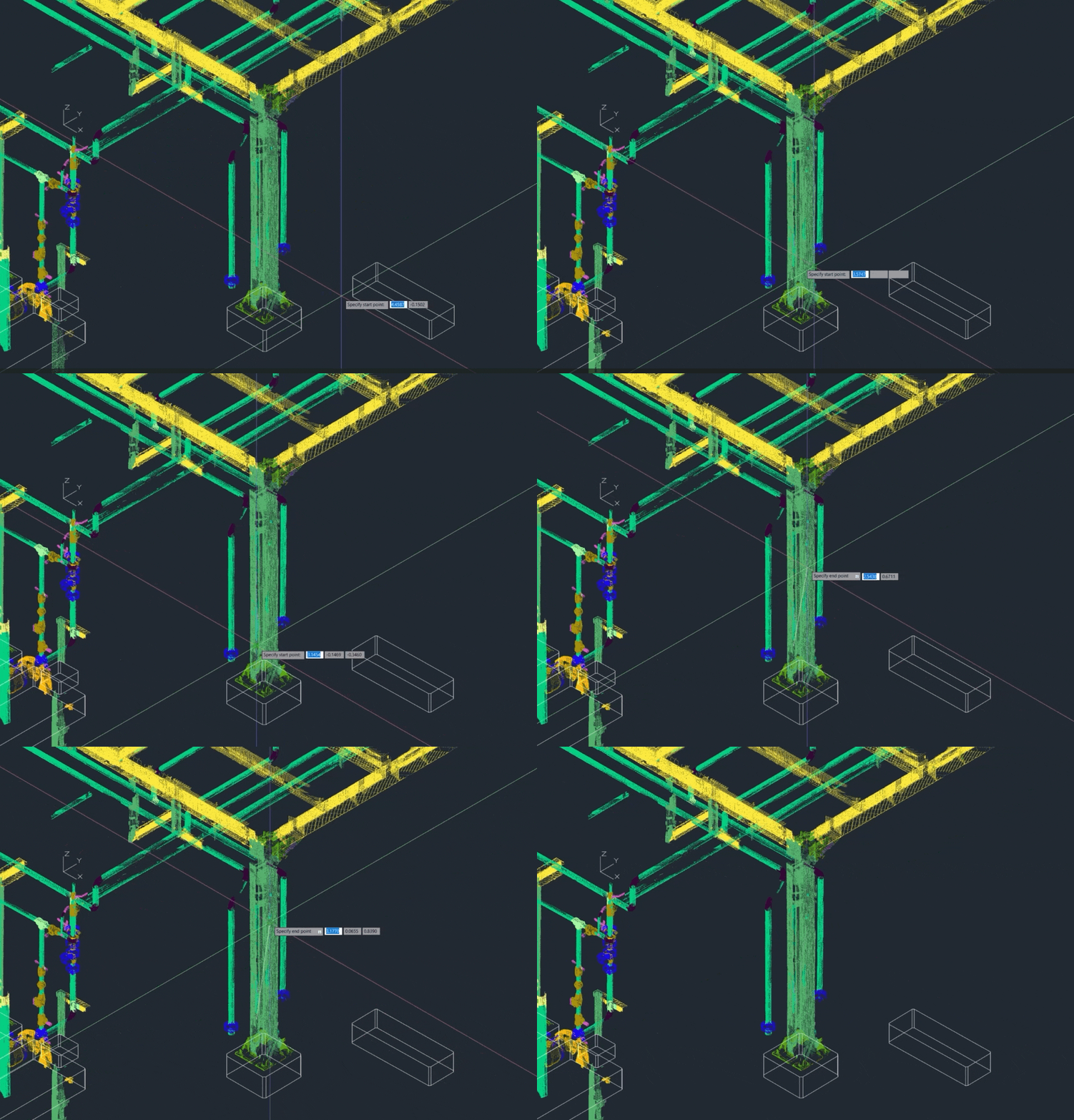
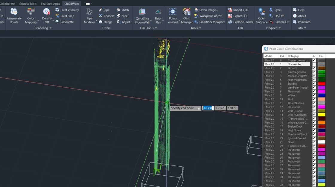
Steel fitting requires two clicks. Click the lower and upper points of the selected steel column.
-
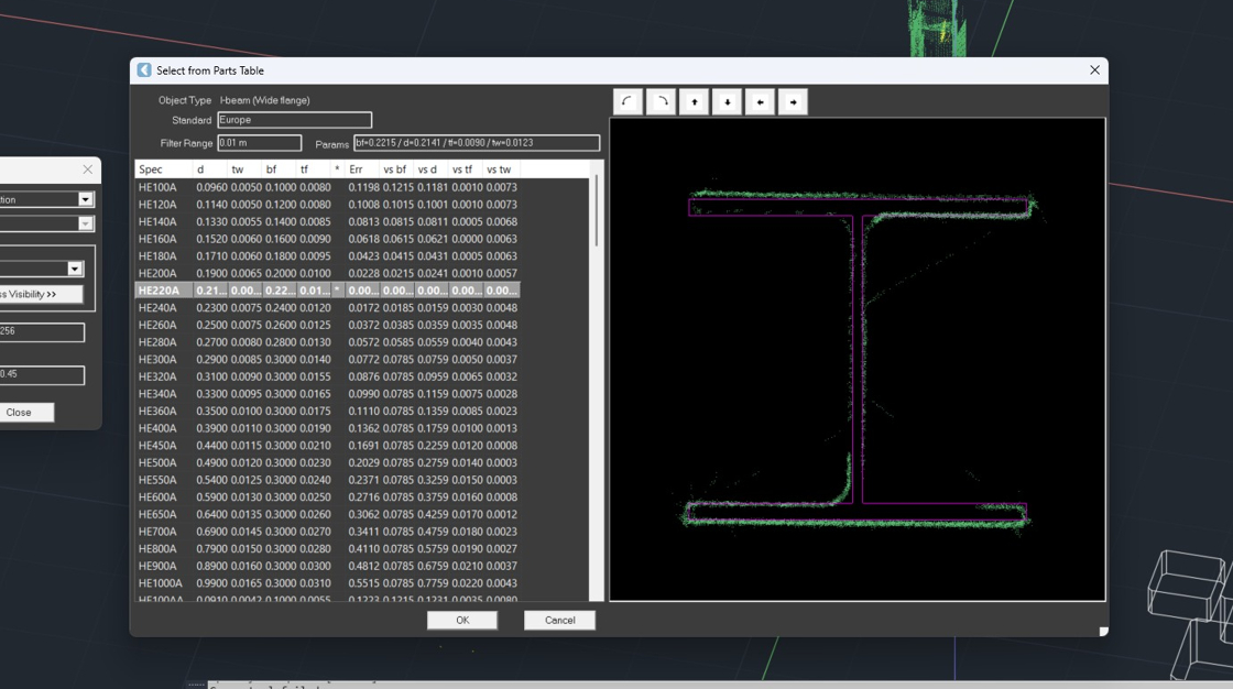
Review the catalog options for the created geometry, select the most suitable one, and click OK.
-
In this example, the initial guess among the provided catalog options is incorrect. Let’s select the HE220AA catalog option and fine-tune the fit using the adjustment buttons.
-
Info: After extracting the steel geometry, a dialog with suggested catalog options for adjusting geometry will appear.
The initial guess is marked with an asterisk. You can scroll through the catalog to find a better fit if needed. The magenta fitting line will be updated to better reflect the selected steel cross-section.
The adjustment buttons above the right panel will let you fine-tune the fit if the cloud is noisy.
.jpeg?cb=905f62e7249f2488d313fa7983f996a5)
Tip: To help organize your project, create an AutoCAD layer for each steel member spec selected. All steel members with the same spec can then be controlled with AutoCAD's layer tools.
-
Continue extracting the columns.
Troubleshooting Difficult Areas
There are some factors that can negatively impact automatic fitting:
-
Noisy data
-
Insufficient data
-
Misaligned data
-
Other objects in close proximity or flush with the object being extracted.
In areas affected by those factors, the fit may fail regardless of where the cloud is clicked. When this occurs, the console displays the Grow steel failed notification.
Let’s review methods for extracting steel geometry in these situations.
Isolating the Area of Interest Using Fence
Using fences is one of the best ways to isolate the correct points and ensure accurate point selection.
-
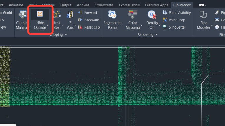
Navigate to Clipping | Hide Outside.
-
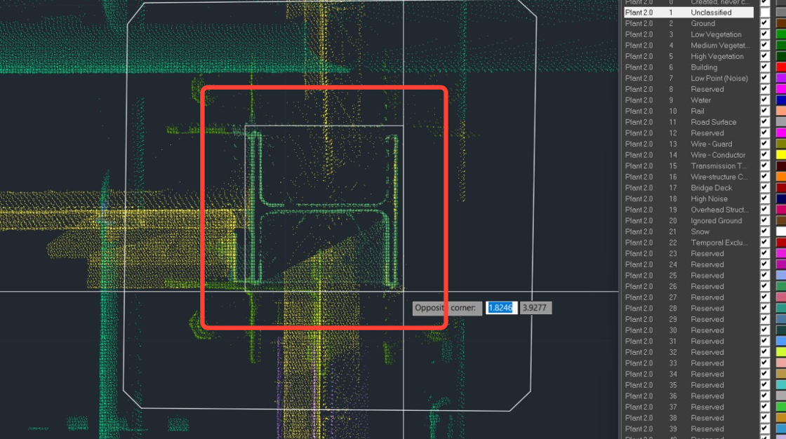
Draw a close rectangular fence around the piece of steel where the fitting frequently fails.
-
Enable the Steel fitter (Fitters | Steel), click Pick in the Fit Steel dialog, and select two points to extract the steel column geometry. It can be helpful to select two different faces.
-
This time, the initially suggested catalog option is successful. Click OK to confirm the selection.
-
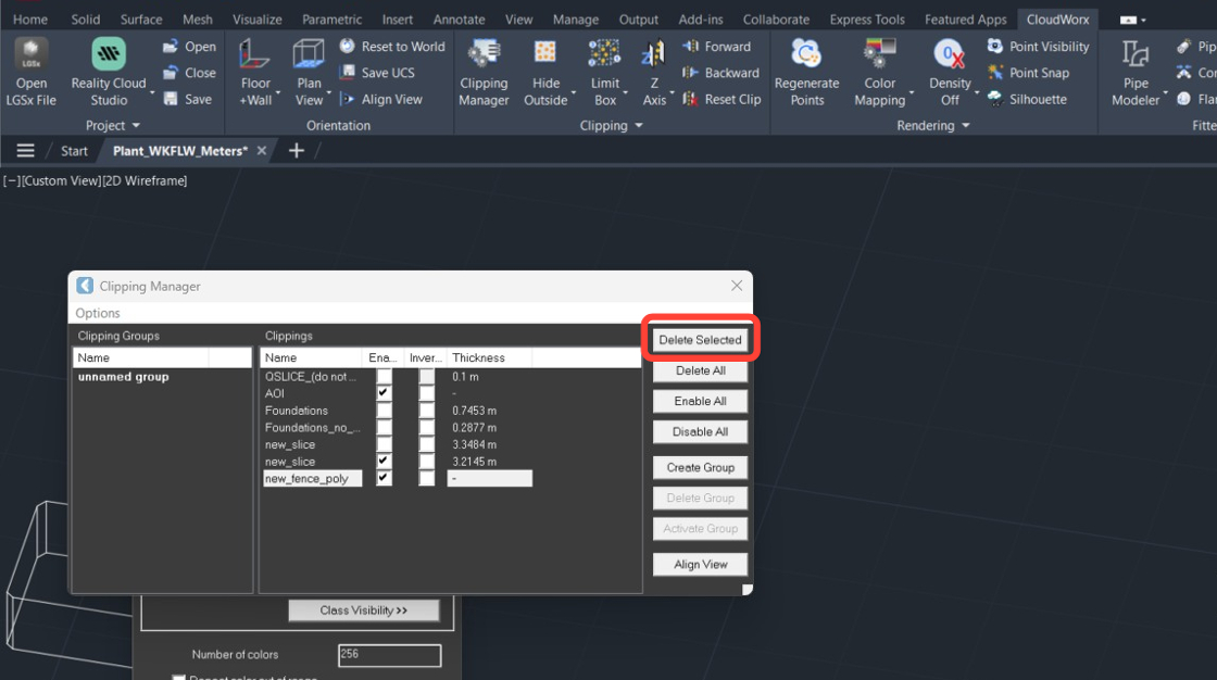
To remove the fence and restore the point cloud, navigate to Clipping | Clipping Manager and delete the recently created fence.
-
Select the latest entry on the list and click Delete Selected.
-
Copying Steel Object When Automatic Fitting Is Not Possible
In some places, the data is too limited for automatic fitting. Here, you can copy steel objects of the same size and orientation and line them up with the cloud using CAD tools.
-
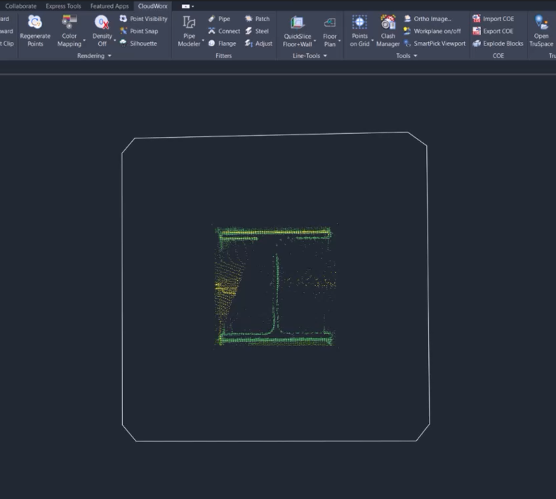
Navigate to Clipping | Hide Outside and isolate the required piece of steel.
-
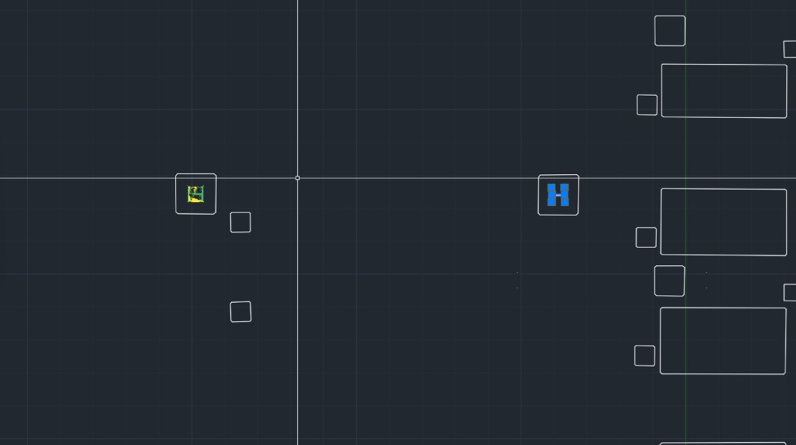
Zoom out in the point cloud to find a piece of steel of the same size and press Ctrl + C to copy it.
-
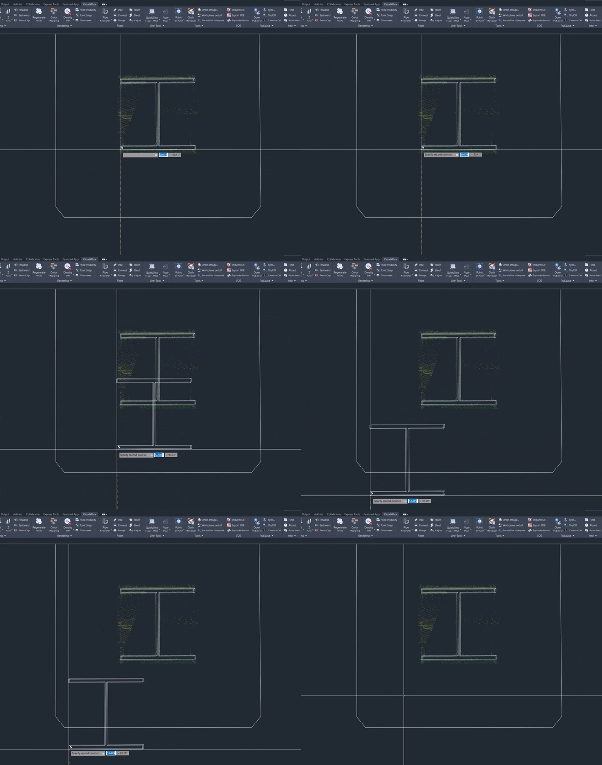
Press Ctrl + V to paste the copied steel member. After that, click outside the selection area to finish the command.
Tip: To achieve more precise positioning, disable point snapping (Rendering | Point Snap). When point snapping remains active, the cursor attempts to snap to all available points, including the noisy ones.
-
Fine-tune the fit as needed. Since the steel member is a 3D solid CAD object, CAD commands, such as ROTATE, can help make precise adjustments.
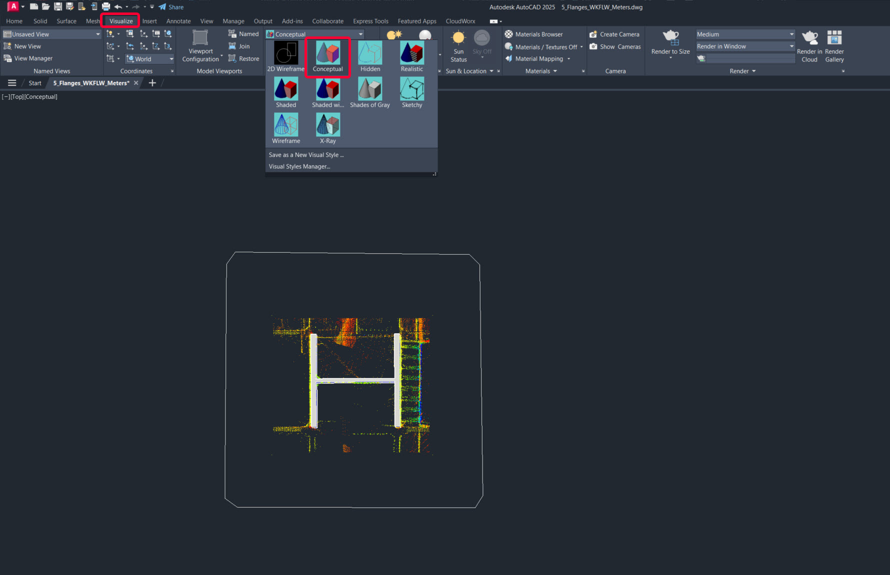
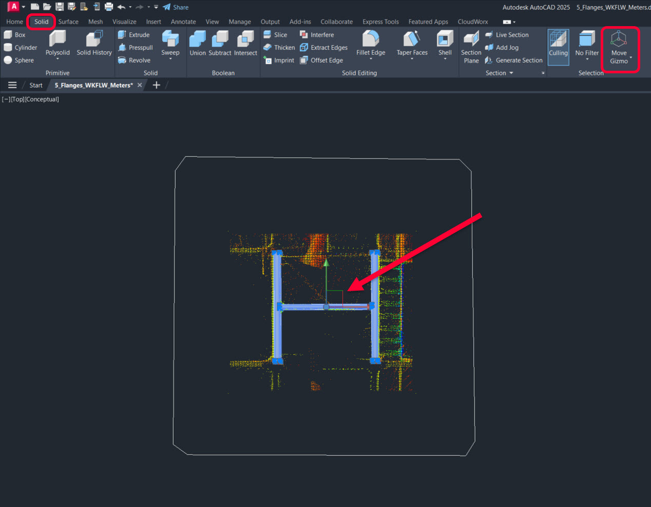
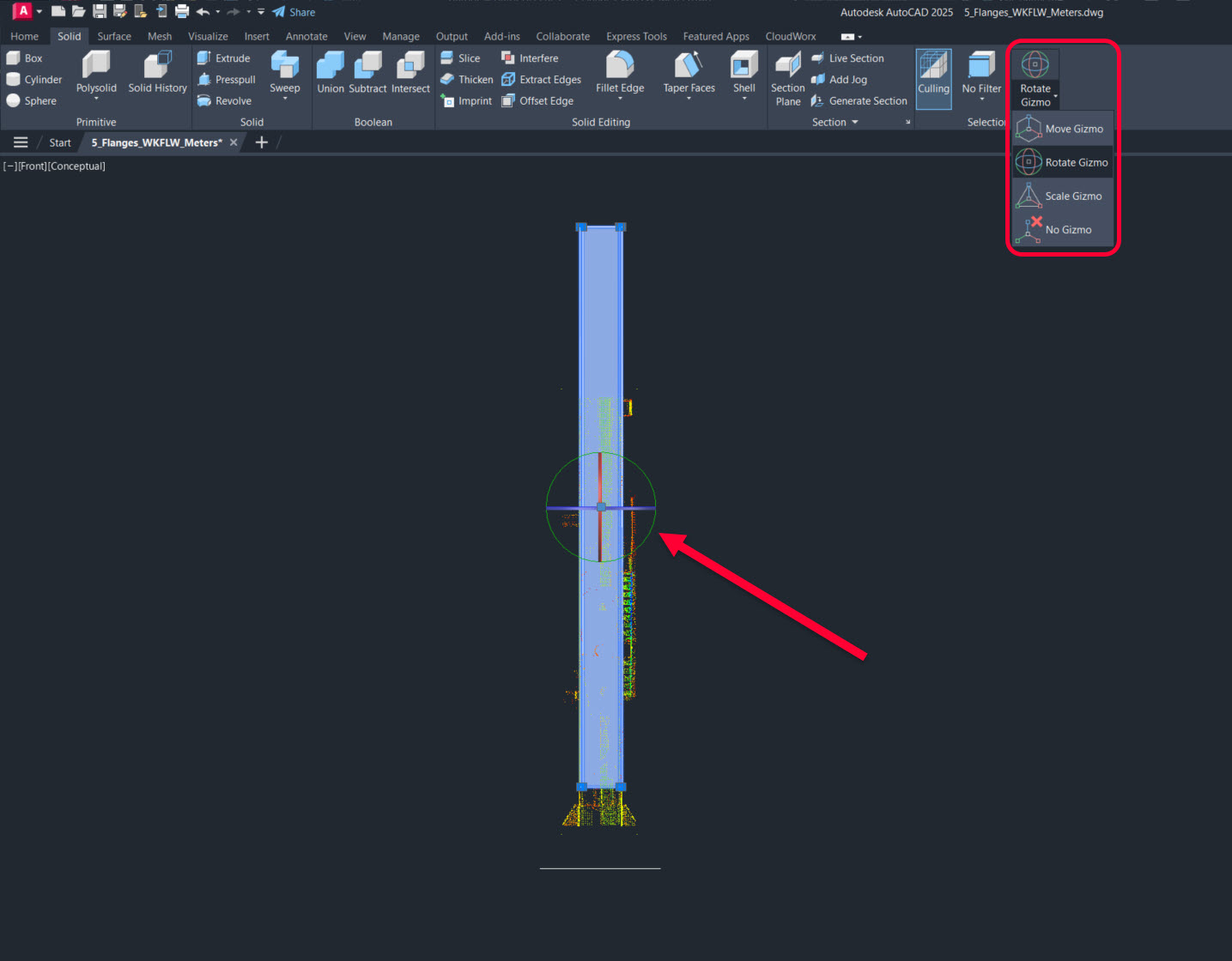
Tip: To fine tune the fitting of the steel, the AutoCAD Gizmo tool can be used to adjust 3D geometric features.
-
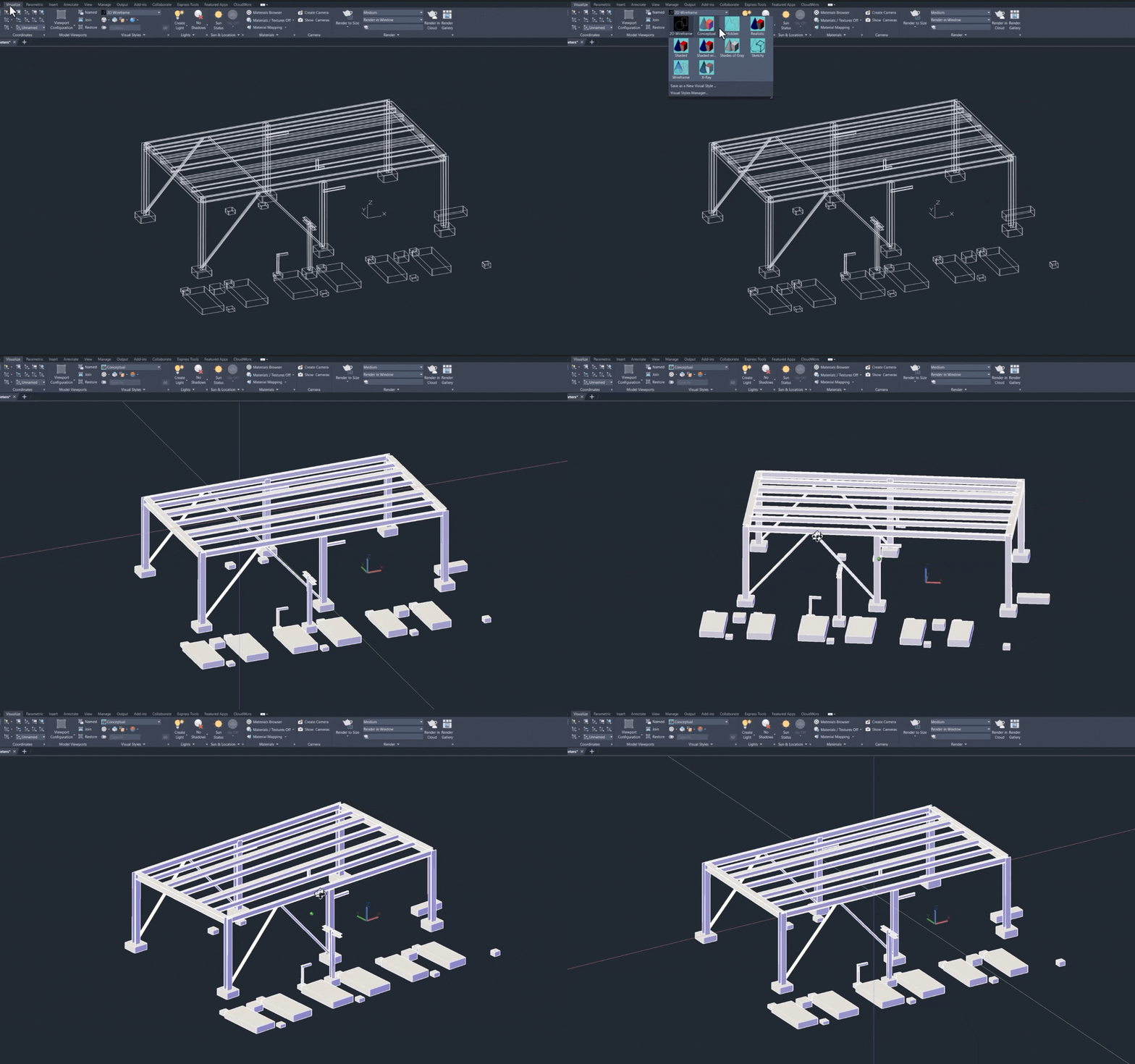
To activate the Gizmo, the visual style needs to be changed on the Visualize tab
-
Select the 3D object and the Move Gizmo is displayed by default. To move the object left click & hold one of the lines of planes on the Gizmo and move the mouse to the desired location.
-
There are other Gizmo types, including rotate and scale. Rotate shows a rotation circle for each axis. To rotate the object, left click and hold one of the circles on the Gizmo and move the mouse around the axis in the desired direction.
-
To learn more about Gizmos, check the AutoCAD documentation here: Gizmos
-
In Clipping Manager, remove or deactivate the recently created fence to restore the point cloud.
Working with Different Steel Types
In this workflow section, you will find helpful tips for extracting a pipe support made from channel and angle steel.
-
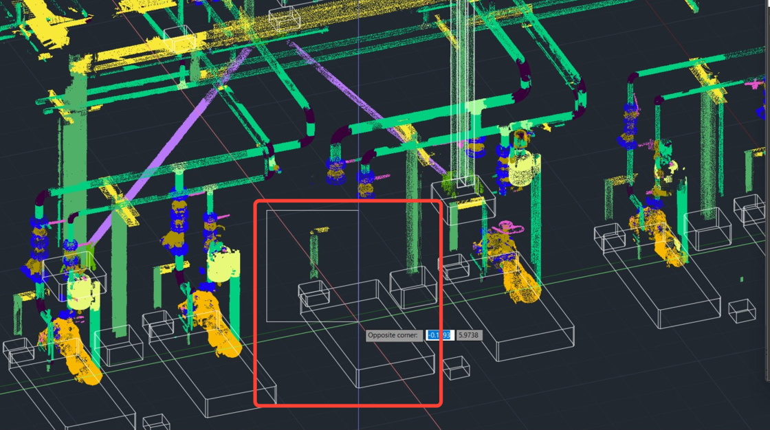
Zoom in on the pipe support you want to extract and isolate it using the Hide Outside fencing tool.
-
Ensure point snapping is enabled.
-
Since the data is thin in this area, select the Unclassified check box in the classification table to reveal all points.
-
To open the classification table, go to Rendering | Color Mapping and click Class Visibility in the Point Cloud Color Mapping dialog.
-
.jpeg?cb=42fe9c921e77b354c90d71ebc2cd2a25)
-
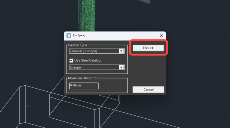
Enable the Steel fitter in the Fitters panel and configure it as follows:
-
Set Section Type to Channel (U-Shape).
-
Select the Use Steel Catalog check box and then select the required catalog.
-
Then click Pick.
-
-
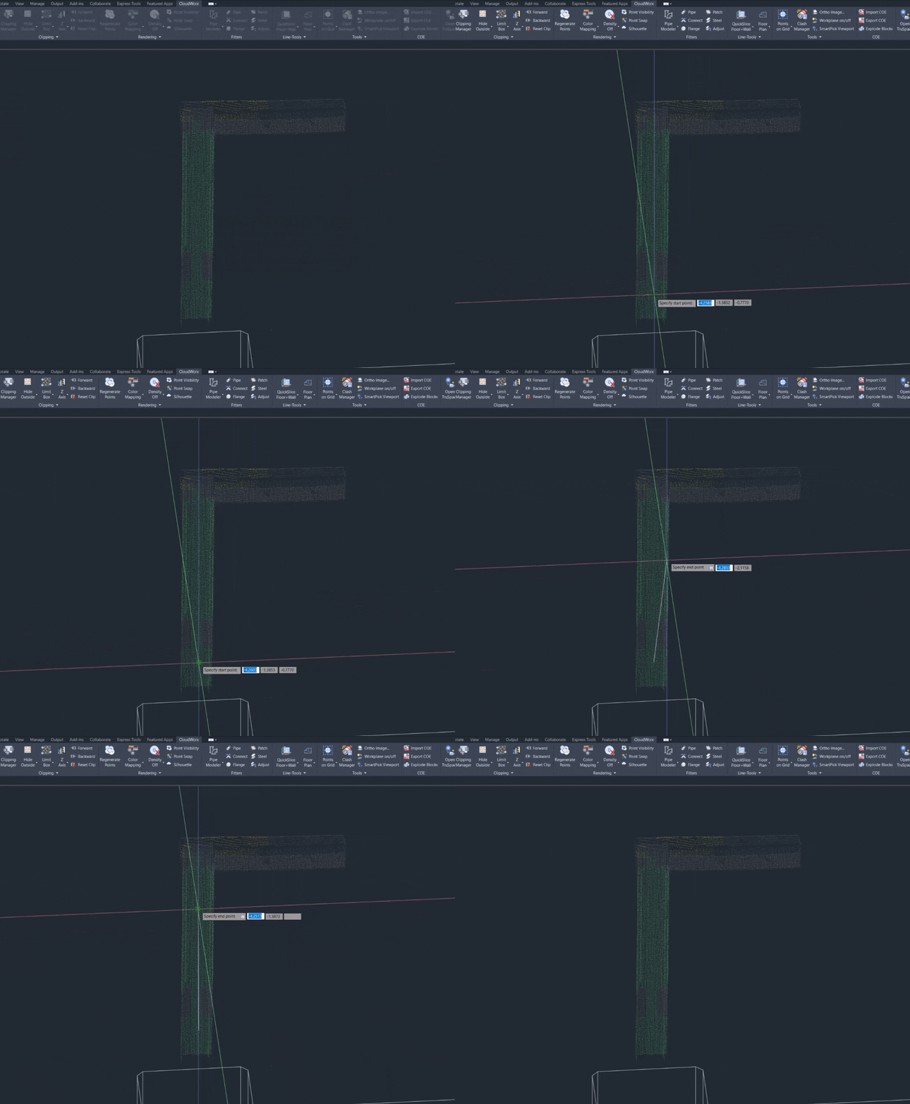
Select the lower and upper points on the vertical channel steel.
-
Select the initially suggested catalog option (U80) from the list, fine-tune the fit using the adjustment buttons and click OK to save the changes.
.jpeg?cb=0bcba3fe9bc95824d2263c316186666d)
-
Enable the Steel fitter again for extracting the crossbrace steel object:
-
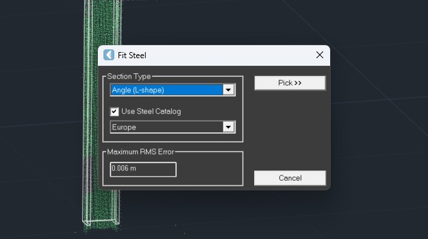
Set Section Type to Angle (L-Shape).
-
Select the Use Steel Catalog check box and then select the required catalog.
-
Then click Pick.
-
-
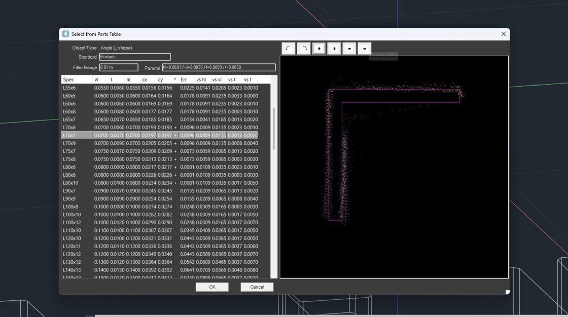
Make two selections on the angle steel.
-
Select the L70x6 catalog option from the list, fine-tune the fit using the adjustment buttons, and click OK.
-
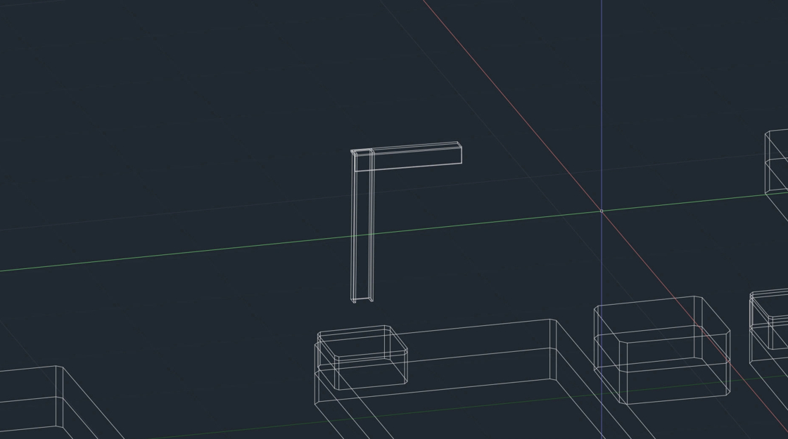
Review the extracted geometry.
Adjusting Steel Length
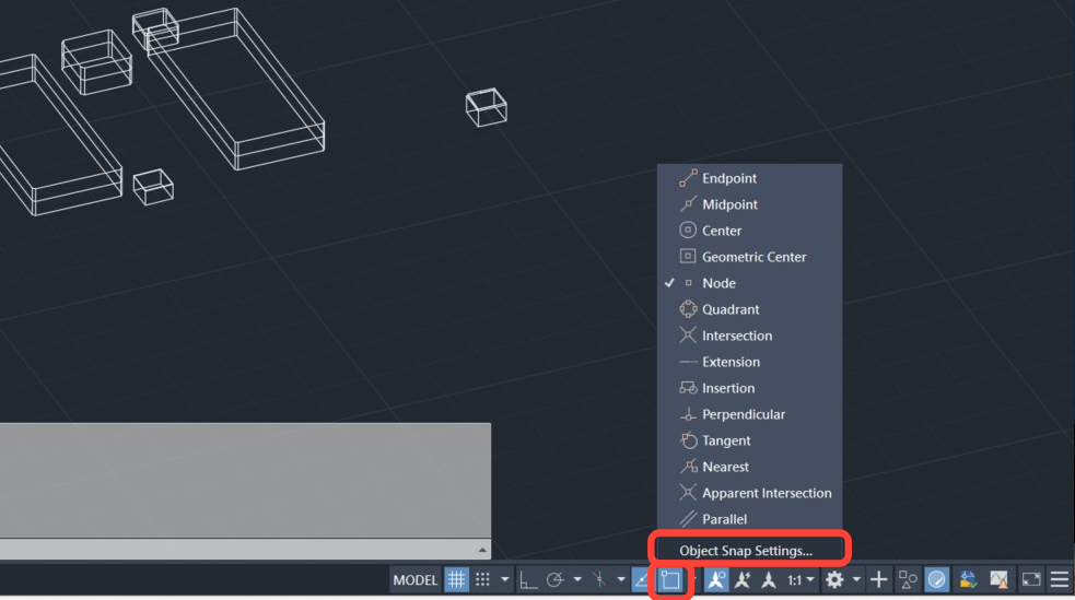
To adjust the steel length, it's helpful to use 3D object snapping.
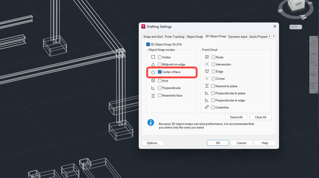
33. Open the Object Snap Settings in the lower-right AutoCAD menu.
-
On the 3D Object Snap tab, select the Center of face check box and click OK.
-
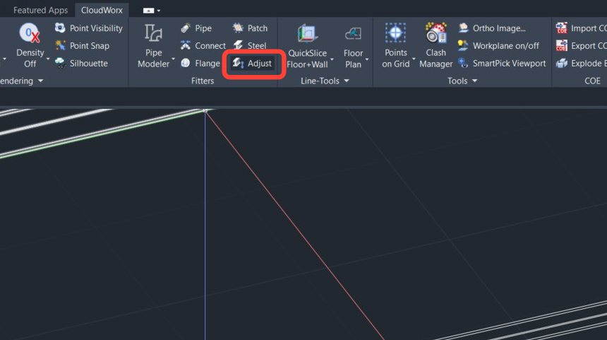
Navigate to CloudWorx | Fitters and click Adjust.
-
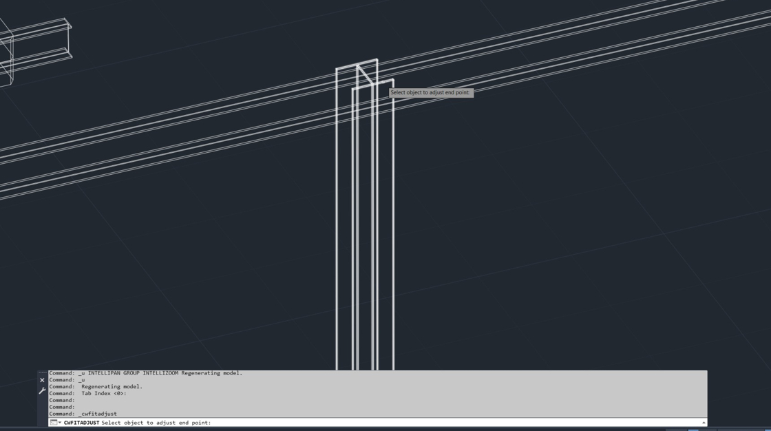
Select one of the steel columns.
-
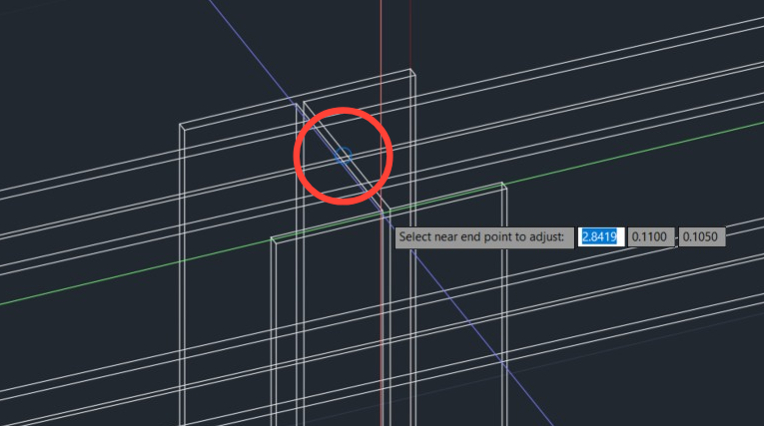
Adjustment requires two selections. First, select the base point on the steel member.
-
Hover the mouse over the end of the steel until a light blue circle appears, indicating the center of the face snap. Click to confirm the selection.
-
-
Next, select the destination point for the steel end. The original position will remain visible while the steel end dynamically follows the cursor.
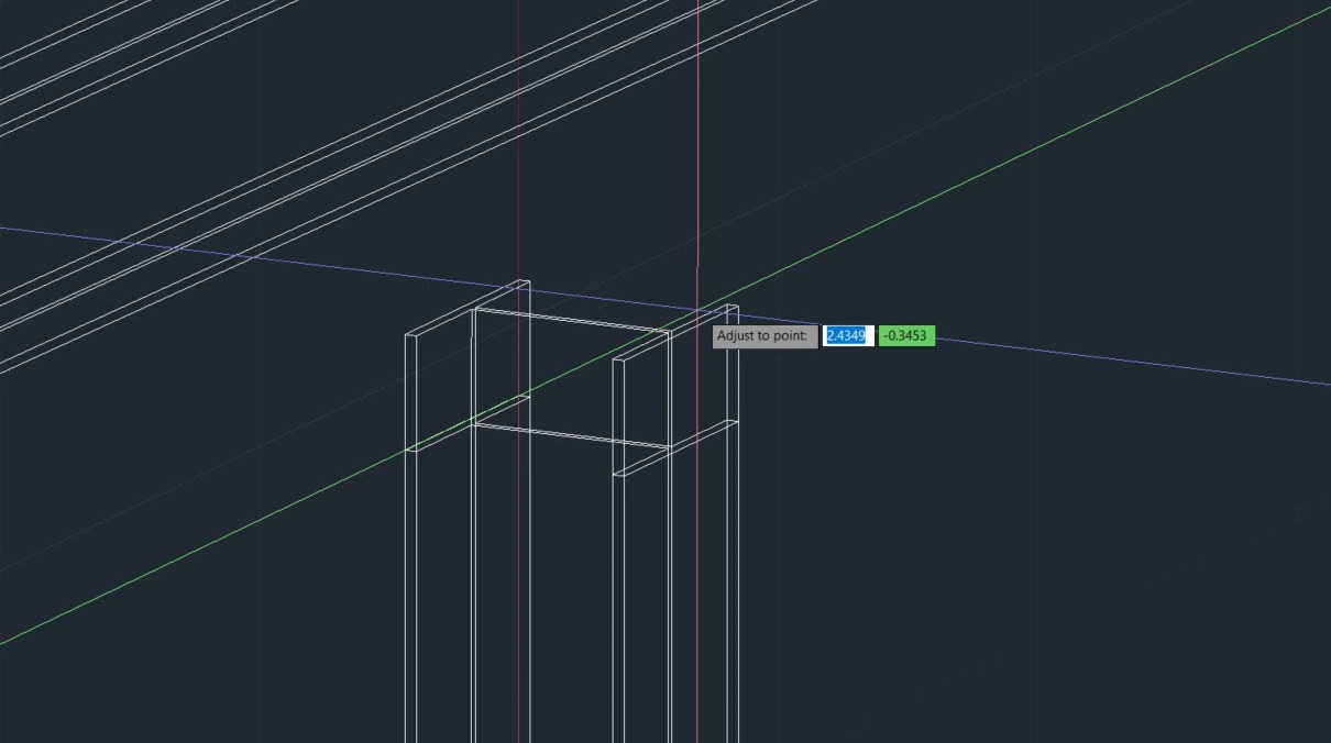
Once the steel end is selected, the tool stays active, allowing both ends of the selected steel object to be adjusted.
-
To adjust the length of another steel object, click the Adjust button in the Fitters panel again and repeat Steps 36-38.
-
To better visualize the result, switch to the Visualize tab and set the view mode to Conceptual for all solids.