AUTOCAD BASIC AUTOCAD PRO REVIT navisworks bricscad basic bricscad pro ULTIMATE
Project | Connect To… | Cyclone ENTERPRISE
Command Line
-
AutoCAD / BricsCAD: CWIMPORTCE
This command enables point cloud data, coordinates, and limit boxes from Cyclone ENTERPRISE to be opened directly in the preferred CAD software.
An initial connection to the Cyclone ENTERPRISE server must be established first.
Note: The Cyclone ENTERPRISE server must be running on the same computer, the network, or an internet host and be reachable from the CAD client. The connection to the Cyclone ENTERPRISE server can be managed in Project | Manage Connections.
The username and password for Cyclone ENTERPRISE are required.
The Cyclone ENTERPRISE Connector license is required on the CAD client.
Using the Tool
To open the Cyclone ENTERPRISE project from CloudWorx, follow the steps below:
-
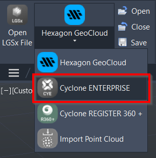
Select Cyclone ENTERPRISE in the Project panel or type a command line prompt specific to the preferred CAD system and press ENTER.
-
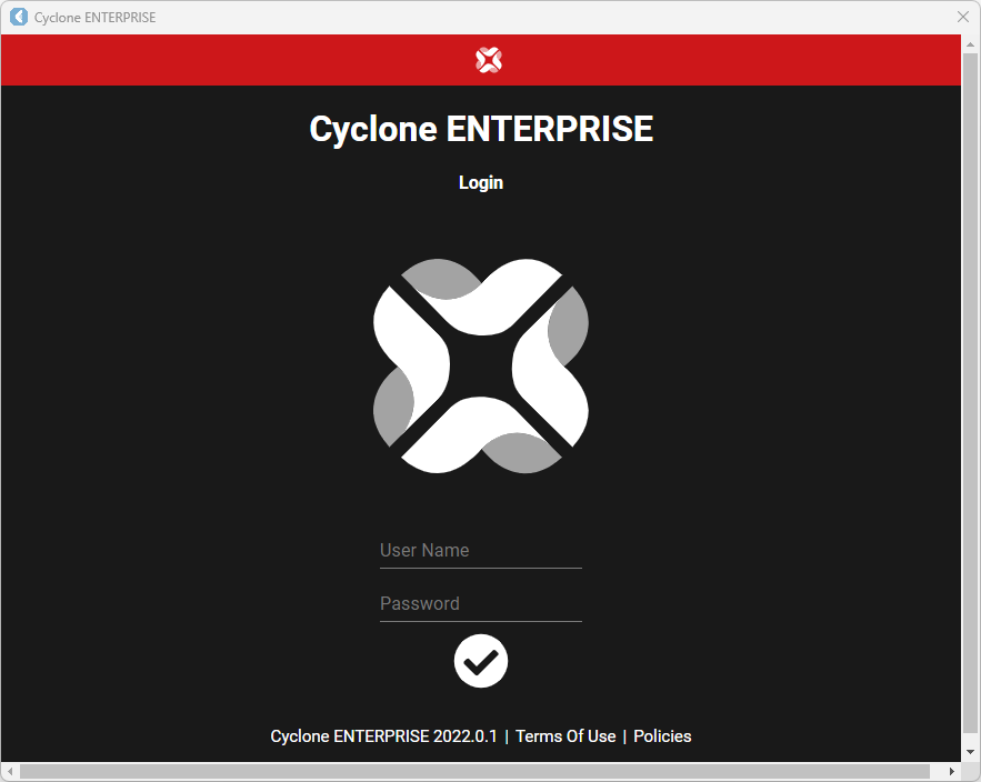
Once done, Cyclone ENTERPRISE will ask for login credentials. Enter the User Name and Password.
-
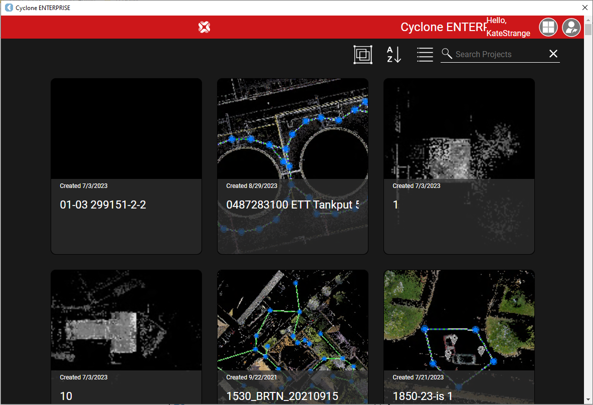
Now, when the connection is made, select the project from the available list.
-
Sorting tools are available at the upper-right corner of the Cyclone ENTERPRISE dialog.
-
-
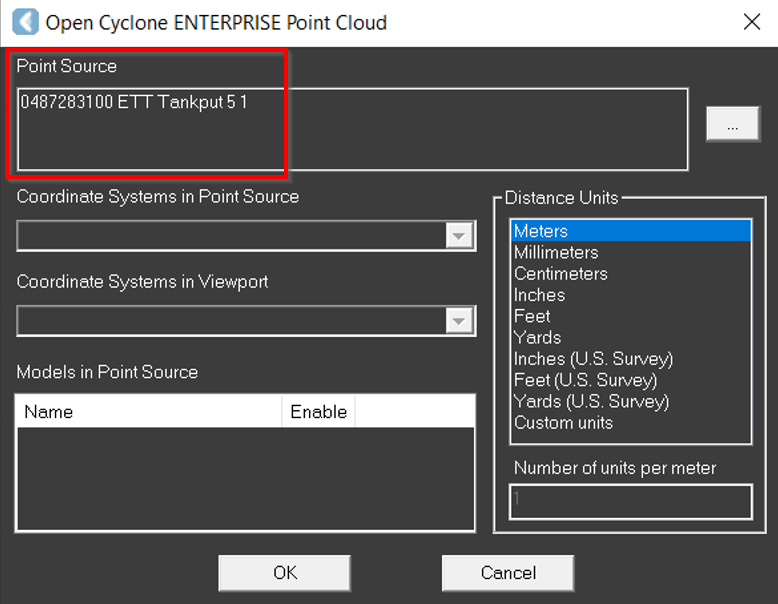
When the project is selected, the Open Cyclone ENTERPRISE Point Cloud dialog opens with the Point Source updated.
-
Click the browse icon (…) to the right of the Point Source field to change the selection.
-
Click the Coordinate Systems in Point Source drop-down menu to select a coordinate system that will be mapped to the drawing's WCS in the preferred CAD software.
-
This drop-down menu contains a list of all the saved coordinate systems associated with the point cloud in the host software.
-
-
In the Coordinate Systems in Viewport drop-down menu, select a coordinate system in the host application.
-
In the Models in Point Source field, select the models to import, if any.
-
Select the preferred CAD drawing unit from the Distance Units field.
-
Distance units are needed to convert the units in the host software (meters) to the units in the preferred CAD software.
-
-
Click OK to load the point cloud.
-
Click Cancel to exit the dialog without loading the point cloud.
-
Use the ZOOM | EXTENTS CAD command to view the entire scene.