
This guide explains the Virtual Surveyor setup workflow.
Prerequisite:
Before proceeding, complete the CAD Environment Setup Guided Workflow* to configure the required CAD parameters for proper usage of Virtual Surveyor.
*The guide is optional for users who already have a Civil 3D field-to-finish workflow configured. If you skip it, please refer to the Adapt Layers and Feature Codes section of the current guide to adjust the layer and feature code sample CSVs as necessary to fit the description keys and figure prefixes in the drawing template.
Practice Data
-
Setup files.zip (extract and use the following files for this workflow):
-
C3D_Layers
-
CWX_VS_Sample_Feature_Codes
-
Import Project Data
-
In the Project panel, click Open LGSx File and browse to the exercise dataset.

Prepare the Point Cloud for Virtual Surveyor
Before launching Virtual Surveyor, the point cloud requires additional preparation in the CAD system.
Define the Area of Interest
-
To speed up point cloud processing, create a fence around the area of interest to temporarily hide unnecessary points.
-
Navigate to Clipping | Hide Outside or type CWHIDEOUT in the command line.
-

b. Follow the prompts in the command line and select the necessary points for creating the chosen fence type. In this exercise, the Polygonal fence type is selected.
Adjust Point Cloud Color
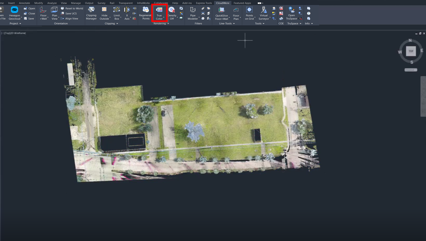
Currently, it is not possible to change the color rendering of the point cloud directly in the Virtual Surveyor tool. It must be set in the CAD window before opening Virtual Surveyor. The tool supports four color modes: True Color, Intensity, Classification, and Single Color.
-
Navigate to Rendering | Color Mapping and select the required color mode. In this exercise, it is True Color.
Start Virtual Surveyor
-
Navigate to Tools | Virtual Surveyor.

Explore Virtual Surveyor UI
The Virtual Surveyor will open in a separate window, providing a user-friendly interface that mirrors the functionality of the tool in Cyclone 3DR.
-
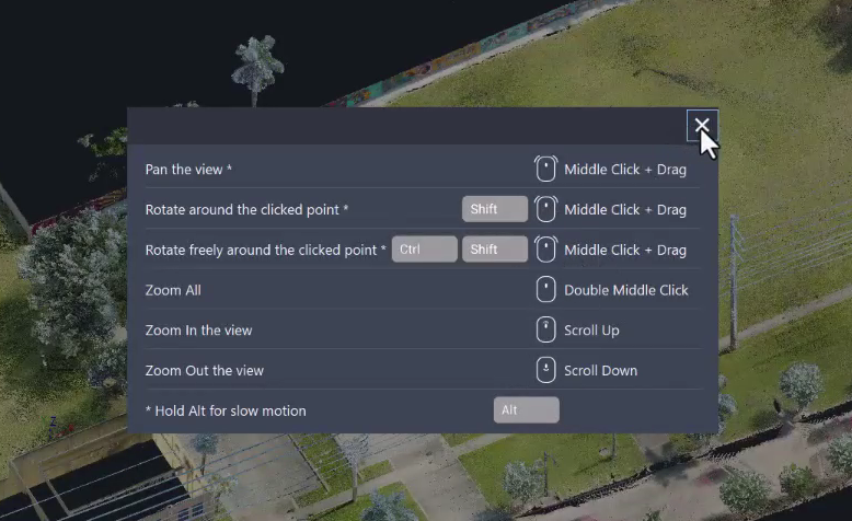
Press Shift + ? to open a reference table showing how to navigate in Virtual Surveyor. The navigation controls are the same as those used in the CAD system.
-
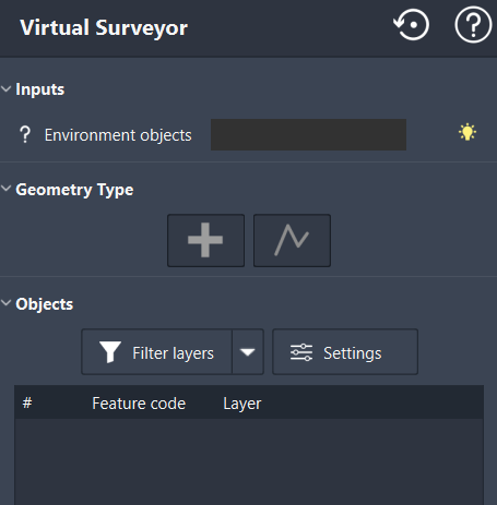
Explore the available tools and settings in the left-side panel:
-
Cloud Visibility: Toggle point cloud visibility on or off.
-
Geometry Type: Create points or polylines.
-
Filter layers: Manage layer visibility.
-
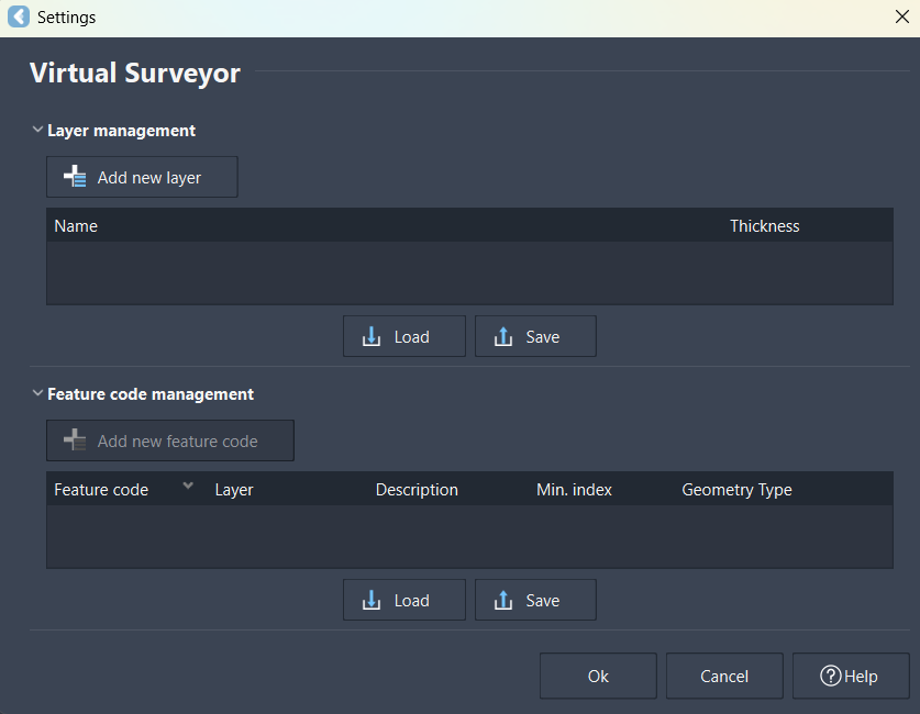
Settings: Configure available feature codes and layers.
-
Explore the available toolset in the right-side panel:
-
Ortho/Perspective mode: Switch between orthographic and perspective views.
-
View Cube: Change the camera orientation to the preferred view.
-
Orbit: Rotate the model around the selected point using the mouse.
-
Pan: Move the model horizontally or vertically.
-
Panorama: View the scene from a fixed location and look in any direction by swivelling and zooming, similar to panning a video camera.
-
Fly: Navigate freely through the scene by moving the mouse. Use the mouse wheel to increase or decrease the flying speed.

-
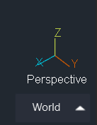
View the current axis orientation and the active coordinate system in the lower-right panel.
Set Up Virtual Surveyor
To prepare Virtual Surveyor for feature extraction, the following configuration steps are required.
-
In the left-side panel, click Settings.
-
The settings dialog will open. It allows adding layers and feature codes.
-
Note: After layers and feature codes are loaded in Virtual Surveyor, they remain available for future use.
Add Layers
-
One of the easiest ways to add layers in Virtual Surveyor is as follows:
-
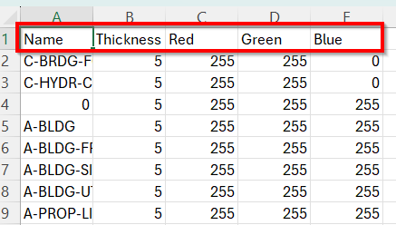
Create a list of layers in an Excel file and convert it to a CSV file.
-
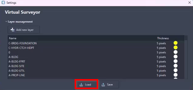
Click Load and browse to the CSV file. In this exercise, the file is available among the exercise materials.
-
Review the layers added in Virtual Surveyor.
-
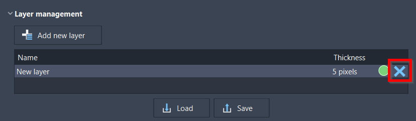
d. Layers can be added one by one using the Add new layer button and then specifying the layer name, thickness, and colour. To remove a layer, simply select the desired layer and click the Delete icon.
Info: Layer Mapping
The sample C3D_Layers.csv file is based on the default Civil 3D layers. The mandatory layers for Virtual Surveyor are mapped by name, thickness and colour.
Thickness and colour are used for visualisation in Virtual Surveyor. When features are transferred back to CAD, these properties are overridden by the layer settings defined in the CAD environment.
Add Feature Codes
The feature codes are added in the same way as layers.
-
Click Load and browse to the CSV file containing feature codes. In this exercise, the file is available among the exercise materials.
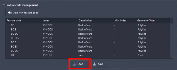
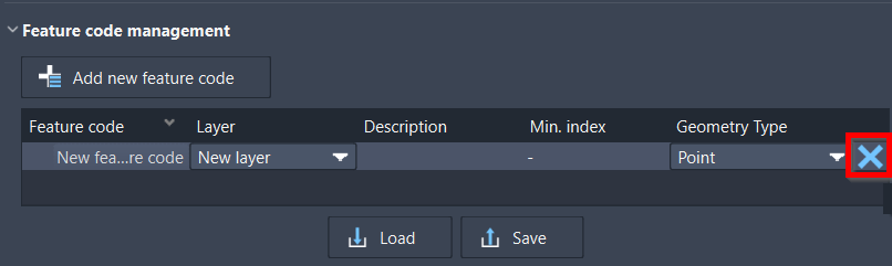
a. Feature codes can also be added one by one using the Add new layer button and then filling in the required fields (Feature code, Layer, Description, Min. index, Geometry Type). To remove a feature code, select it and click the Delete icon.
Info: Feature Code Mapping
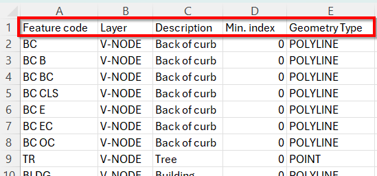
For compatibility with CAD points, the feature codes in the CWX_VS_Sample_Feature_Codes.csv file are mapped using the following fields:
-
Feature Code: The code assigned to a point description in Civil 3D.
-
Layer: The layer associated with the feature. When using a field-to-finish workflow in Civil 3D, a single layer may be sufficient since only a point will be kept.
-
Description: A description used only within Virtual Surveyor. This value is not transferred to CAD.
-
Min. index: The starting point number used to organise points. Point numbers are reassigned by Civil 3D during import.
-
Geometry Type: Defines how the feature is visualised in Virtual Surveyor.
-
Polyline: Connects extracted points into a linear feature. Points assigned to a polyline feature code are grouped together in the Objects panel.
-
Point: Creates individual point features without connecting them to other points.
-
Adapt Layers and Feature Codes (for Existing Field-to-Finish Workflows)
Note: This section applies only to users who already have Civil 3D configured for field-to-finish workflows and need to adjust the sample feature code and layer code CSV files to match the description keys and figure prefixes in the drawing template.
-
From the setup files, create a copy of the following files:
-
C3D_Layers.csv, which demonstrates how default Civil 3D layers can be mapped to the format required by Virtual Surveyor.
-
CWX_VS_Sample_Feature_Codes.csv, which contains sample feature codes for use with Virtual Surveyor.
-
-
Adapt the copied files as follows:
-
Retain the header rows. They define the required file structure.
-
Remove the sample entries.
-
Add your own layers and feature codes that match your project needs or company requirements.
-
-
Load the updated CSV files with custom feature codes and layers to Virtual Surveyor (see Steps 9-11).
The required configuration is complete. Virtual Surveyor is now ready for feature extraction.
⬅️ Previous: Civil 3D Environment Setup