
Before you begin:
Users who already have Civil 3D configured for field-to-finish workflows can skip this workflow and proceed to the Virtual Surveyor Setup guide. It demonstrates how to adapt the sample feature code and layer code CSV files to match your own layer and coding conventions.
This guide explains how to configure the required CAD settings before using Virtual Surveyor.
In this and subsequent guides, the workflow is demonstrated in Autodesk Civil 3D, but the same configuration principles apply to other supported CAD systems.
Practice Data
-
Setup files.zip (extract and use the following files for this workflow):
-
VS_CWX_DEMO
-
CWX_VS_DEMO.f2b
-
CW_VS_DEMO.fdb
-
Prepare Required Files
-
Before starting Civil 3D, add the required setup files to the default app storage as follows:
-
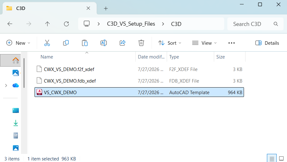
Copy the template for this exercise to the default CAD system storage at C:\Users\<user>\AppData\Local\Autodesk\C3D 2027\enu\Template.
-
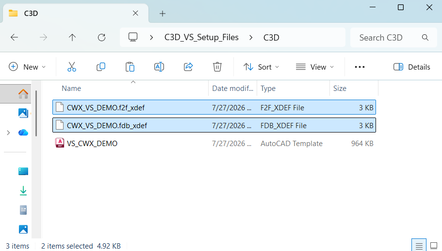
b. From the exercise files folder, copy the field and finish files to C:\Program Data\Autodesk\C3D 2027\enu\Survey.
-
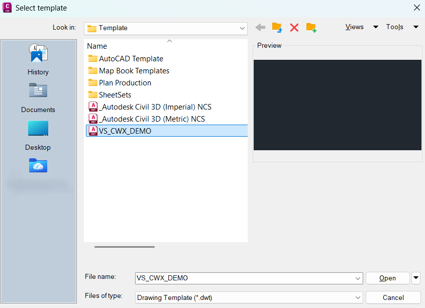
Start Civil 3D and open a new drawing using a template previously added to the Template folder.
Verify CAD Settings
Now, it is necessary to verify the Civil 3D settings to ensure the template is applied correctly.
Check Description Keys
-
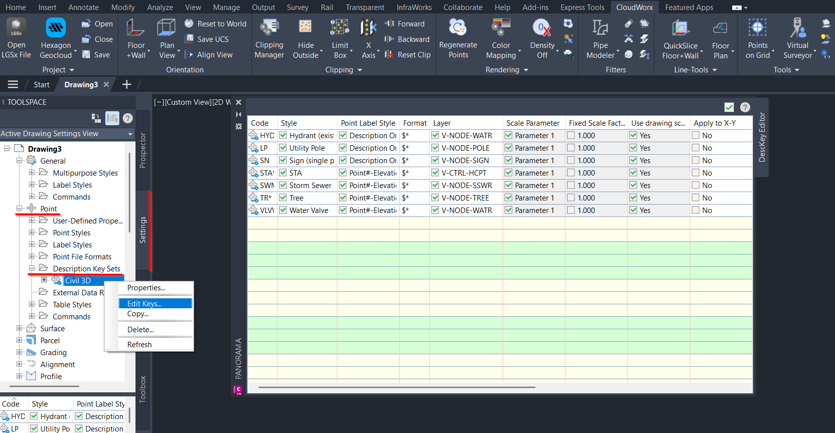
In the Toolspace panel, go to Settings | Point | Description Key Sets. Right-click Civil 3D and select Edit Keys.
-
The table with available feature codes will open. Ensure that all feature codes from the DWT template are available.
Info: What do description keys do?
Description keys interpret the code associated with each point-type feature that isn't connected by linework and apply a corresponding style to it.
So, when the data is imported, description keys analyse it to identify matches with available feature codes and apply the corresponding symbols to the points that align with those codes.
Verify Linework Parameters
-
Go to the Survey tab, right-click Figure Prefix Databases, and click Refresh.
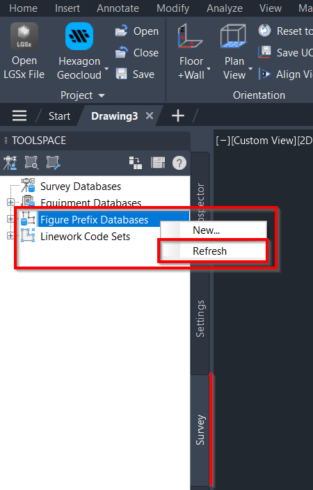
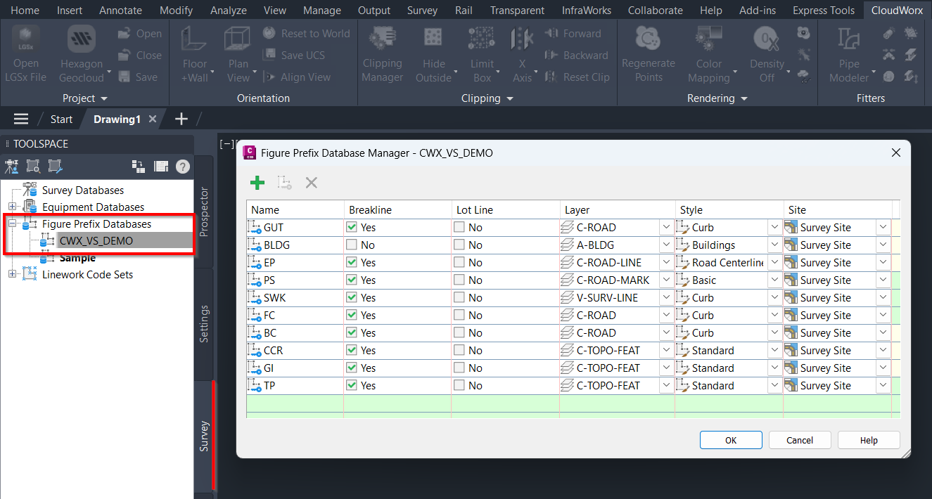
a. If the field and finish files were copied correctly (see Step 1b), they will appear under the Figure Prefix Databases list.
Info: Figure prefix databases work similarly to description keys, but they are used for features that include linework.
When data is imported into the survey database, Civil 3D uses the figure prefix database to search for points with linework and converts them into survey figures. The figure prefixes automatically assign properties, such as layers and styles, helping ensure that linework features are created and displayed consistently.
-
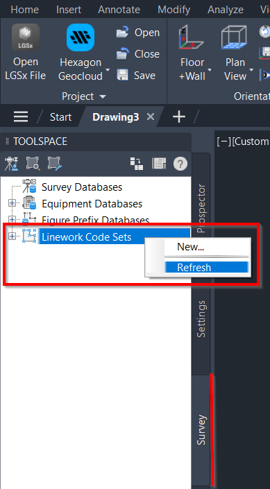
Go to Survey | Linework Code Sets, right-click it, and select Refresh.
-
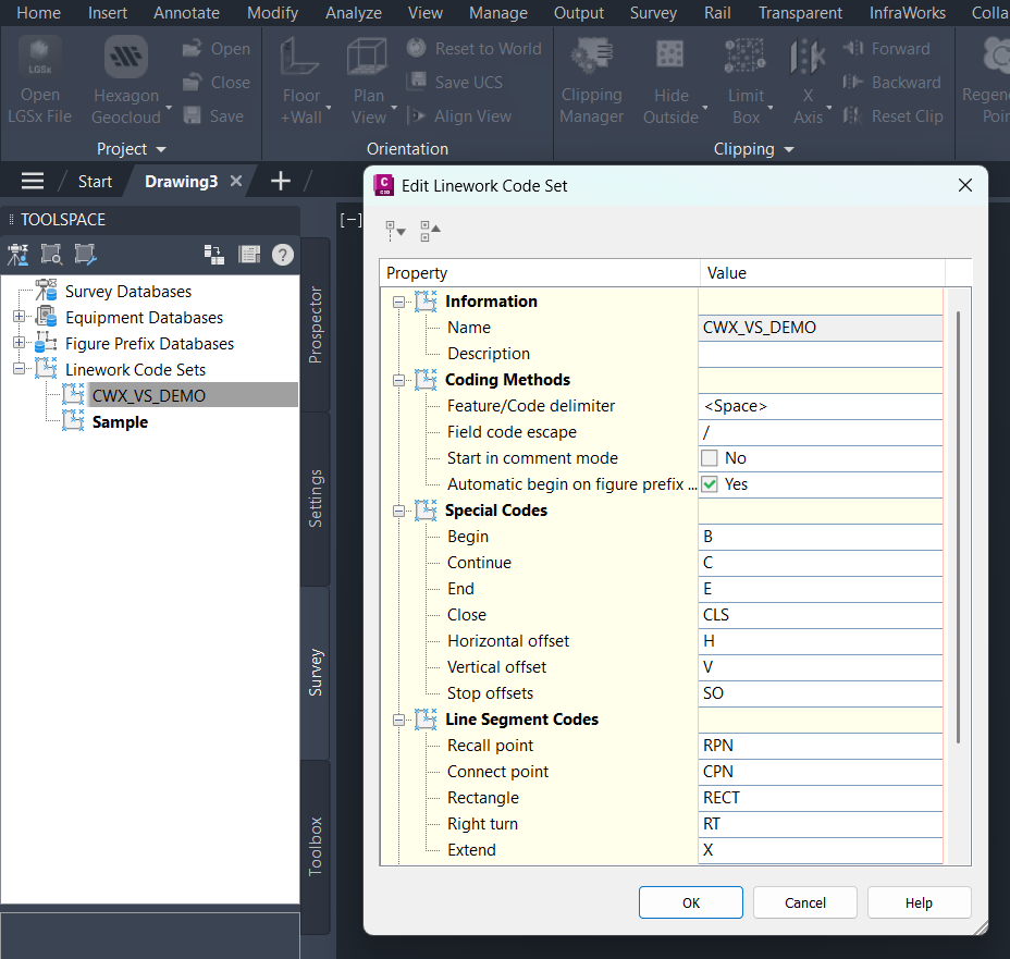
The applied linework code set will appear on the list. Right-click it and select Edit so that you can check how these codes work.
Info: Linework codes are special codes that translate survey field codes into intelligent CAD linework. The provide additional information about how the linework should be drawn to Civil 3D. They can be easily customised according to your needs.
Example: To create the linework for edge of pavement using field to finish, the feature code would be “EP”. There may be multiple separate features using the code “EP” in the drawing. To help Civil 3D connect only the relevant points, start a polyline with the linework code “B”. So “EP” becomes “EP B”. To end the same polyline feature, you would give the last point you intend to connect the code “EP E” to end the line. Intermediate points along the line would be called “EP”. The next “EP” feature would start with “EP B” and end with “EP E” to create separate line polyline feature.
An example of how to use linework codes to automatically add arcs, representing curves to polylines can be seen in exercise 3 in this series: “Extracting Features in Virtual Surveyor”
Set Up Survey Database
-
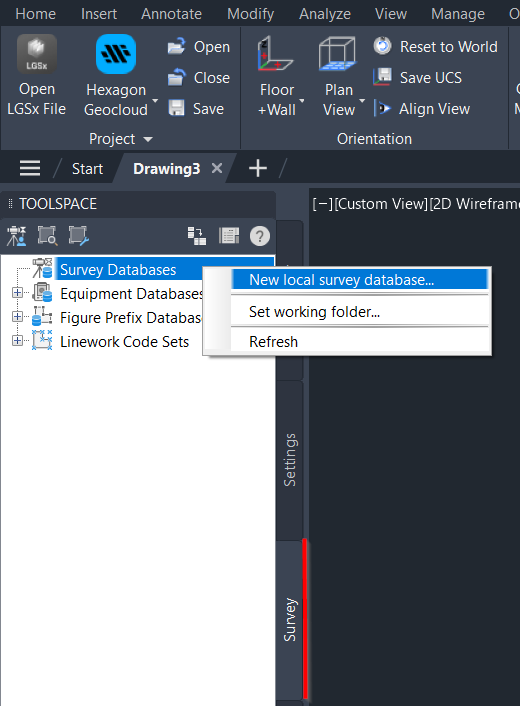
Go to Survey | Survey Databases, right-click it, and select New local survey database.
-
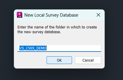
In the New Local Survey Database dialog, specify the database folder name and click OK.
-
The project survey database is created.
-
Check Drawing Units
The video demonstrates using feet, because the dataset is from the United States. However, the units are irrelevant for the purpose of this exercise series and meters can be used if it is the preferred unit.
-
Type DWGUNITS in the command line to review the available options. If necessary, adjust the units to meet your project requirements.
-
Type UNITS and check the insertion scale units.
The CAD settings have been successfully verified, and the project drawing is prepared for work with Virtual Surveyor.
➡️ Next: Virtual Surveyor Setup