
This guide demonstrates how to place points within a fenced area at a defined interval using the Point on Grid tool.
Prerequisite: For full workflow context and results, review the following guides in this series:
Enable the Grid
-
In the Tools panel, click Points on Grid.

-
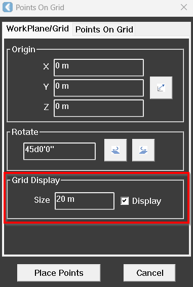
In the Points on Grid dialog, on the Workplane/Grid tab, specify the grid size in the Size field.
-
Select the Display checkbox to show the grid in the workspace.
Define Grid Parameters
-
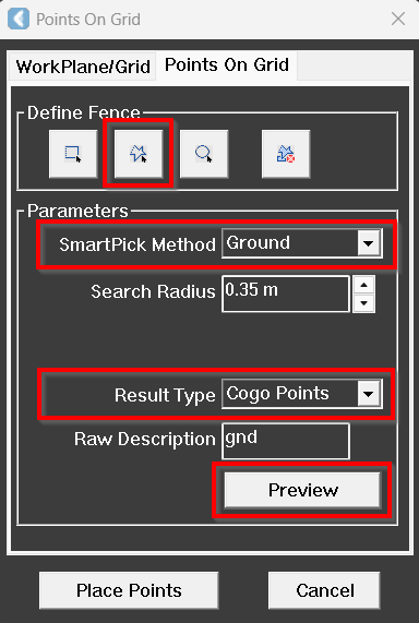
Open the Points on Grid tab.
-
Define the required fence type. In this exercise, it’s Polygon.
Tip: When defining the fenced area, press F3 to disable snapping and prevent unintentional snapping to the existing linework.
-
Configure the following parameters:
-
SmartPick Method: Ground
-
Result Type: Cogo Points
-
-
Click Preview to visualise the grid.
Adjust Workplane Parameters
If necessary, adjust the workplane orientation before generating the grid:
-
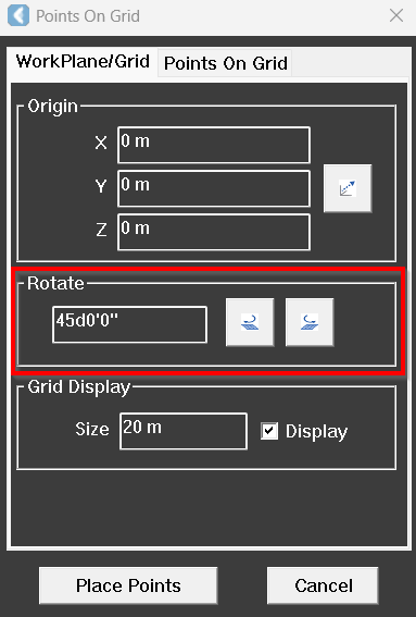
On the Workplane/Grid tab, use the Rotate tools to rotate the workplane clockwise or counterclockwise, or specify a rotation angle.
-
Switch back to the Points on Grid tab and generate a new preview.
Place Points on Grid
-
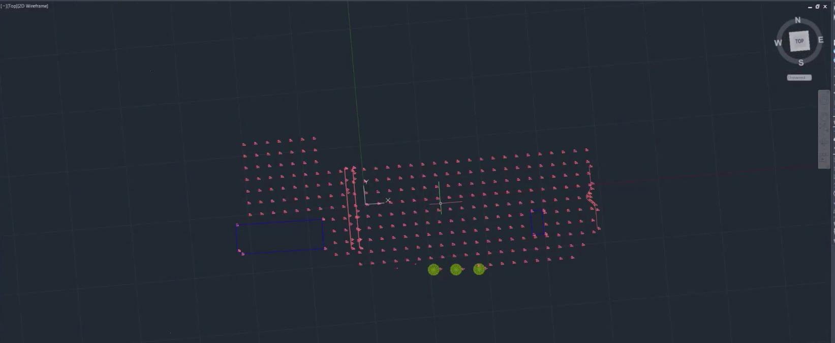
When satisfied with the preview results, click Place Points.
-
Turn off Point Visibility to review the ground points.
The points are placed within the defined fenced area according to the specified grid interval.
⬅️ Previous: Finalising Survey Data in CAD Drawing