AutoCAD Pro revit bricscad pro ultimate
Fitters | Pipe
Command Line
-
AutoCAD / BricsCAD: CWFITPIPE
This command is used to fit a pipe from a cylindrical region or fenced section of the point cloud.
Using the Tool
To fit a pipe via a seed point:
-
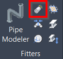
Either click the Pipe button in the Fitters panel or type a command line prompt specific to the preferred CAD system and press ENTER.
-
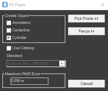
The Fit Pipes dialog appears.
-
The Maximum RMS Error field displays the sampling error of the original point cloud. If the fit quality does not meet this number, the fit is rejected.
-
-
Select any combination of output options:
-
Annotation displays an annotation of the pipe's diameter on the result's centerline.
-
Centerline inserts the centerline of the resulting pipe. This option is recommended if the user intends to connect multiple cylinders or perform further operations based on the pipe's centerline. The resulting centerline behaves like a line segment, and the endpoints can be translated along its original axis.
-
Cylinder inserts a cylinder entity representing the surface of the resulting pipe.
-
-
Click Pick Points, and then pick a point on the surface of a cylinder. The pipe is fit and the results are displayed. It may take time to find the surface.
Notes:
-
The cylinder fitting process is impacted by all the clipping planes, as they determine which points are used for fitting.
-
Attempt to pick a point in a relatively smooth area. After each click, check the output window for additional information if you do not see the expected result showing up in the window.
-
Continue picking each surface onto which you want to fit a pipe, and then press ENTER.
To fit a pipe via a fence:
-
Follow Steps 1-2 described in the To fit a pipe via a seed point section.
-
Click Fence.
-
All points within the fence are used to fit the cylinder.
-
To change the type of fence to be drawn, type POLYGON, CIRCLE, or RECTANGLE, and then press ENTER.
-
-
Draw a fence.
-
If the fit quality does not meet the Maximum RMS Error, the fit is rejected.
-
To define a rectangle fence, click once to select a corner point, and then click again to select the opposite corner.
-
To connect pipes created with a centerline, use the Connect Pipes tool.
To create a pipe with insulation (CloudWorx for Revit only):
-
Click Pipe in the Fitters panel.
-
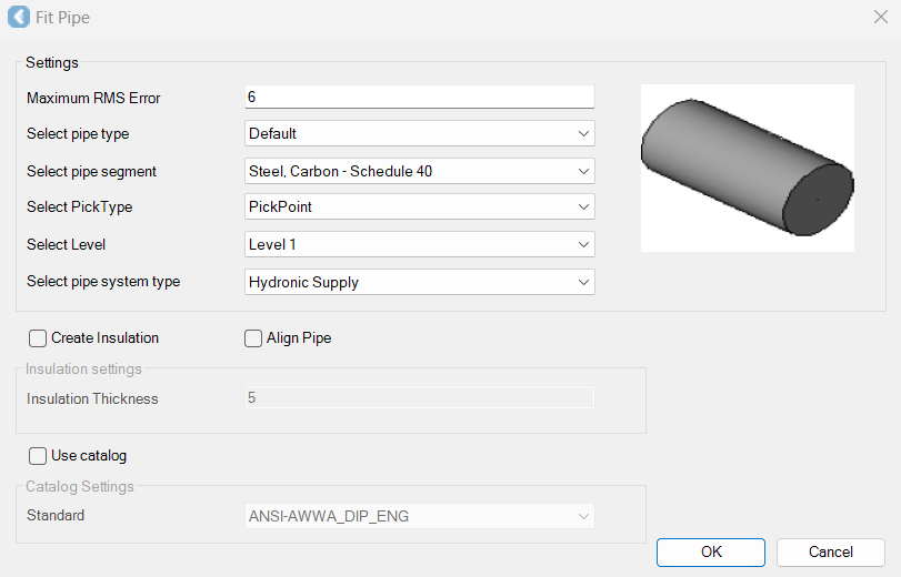
The Fit Pipe dialog appears.
-
-
Specify the maximum allowable error.
-
Select the pipe type, pipe segment, and pick type.
-
Select the level to which the pipe should be added.
-
Levels are set within a Revit drawing prior to inserting modelled objects. Please refer to Revit help for instructions on setting levels.
-
-
Select the pipe system type.
-
Pipe system information is native to Revit drawings and should be selected in accordance with project needs.
-
-
If desired, select the Create Insulation check box to define the insulation of a pipe at the time of creation and specify the insulation thickness.
-
When the pipe is placed in the drawing, it will subtract the thickness of the insulation from the pipe, thus the fit pipe will appear smaller than the scanned pipe.
-
-
In Revit CAD window or TruSpace, pick the required pipe.
-
A new dialog will appear which suggests a type within a family for the pipe based on best fit.
-
Accept the suggested type.
-
If the type is not a close enough fit, create a new type by defining its name and size.
-
Click OK, and the pipe will be placed.
-