autocad pro revit bricscad pro ultimate
Fitters | Steel
Command Line
-
AutoCAD / BricsCAD: CWFITSTEEL
This command is used to fit several different types of steel geometry to points.
Using the Tool
To fit a section of steel:
-
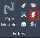
Either click the Steel button in the Fitters panel or type a command line prompt specific to the preferred CAD system and press ENTER.
-
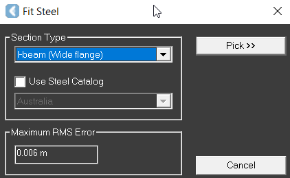
The Fit Steel dialog appears.
-
-
Select the type of steel from the Section Type drop-down list.
-
Click the Pick button, then pick the first seed point, followed by the second.
-
The first (primary) selection point is on the part of the structure that adequately represents the structure's cross-section, that is, as good and as clean as possible with respect to the overall structure.
-
The area, about 20 centimetres along the primary axis, around the first (primary) selection point, must be free of attachments, and adjacent structures must have a distance of at least half the target structure's cross-section extent.
-
-
This step is optional. The Maximum RMS Error field displays the sampling error of the original point cloud. The RMS (Root Mean Squared) error value can be modified.
-
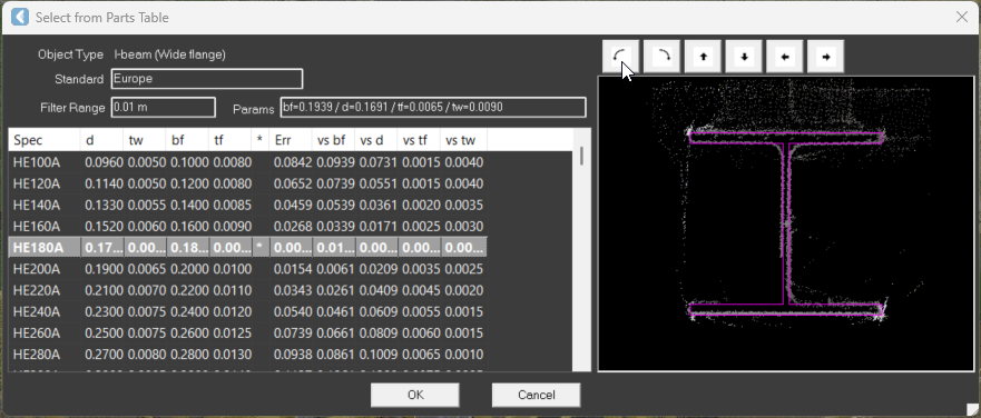
This step is optional. If the Use Steel Catalog check box is selected, the user has the option of selecting the country standard that the catalogue is associated with. Once the required picks are made and the steel shape can be successfully fit, a standard parts table appears.
-
The steel shape that is selected from the Select from Parts Table dialog may have a star symbol (*) next to the tf column. It indicates that the fit is good. If the plus sign appears, it means that the fit is within the specified Filter Range.
-
If adjustments are needed for the created steel shape, the view can be adjusted using the view manipulation buttons or mouse-based controls, which become active when the pointer is moved over the corners or midpoints of the fitting area.
-