Autocad pro revit bricscad pro ultimate
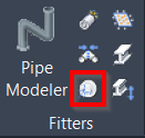
Fitters | Flange Work Point
Command Line
-
AutoCAD / BricsCAD: CWFITFLANGE
This command assists in determining the placement position for flanges and flanged components.
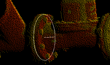
A flange work point or a tie point is a point with an axis direction for inserting a flange. This creates a circle centred at the work point, normally along the axis for the work point graphic representation.
In general, a flange axis can be determined either by its neighbouring pipe or the points that represent the flange component. However, growing a flange from a pick on the flange surface is generally unreliable and inaccurate. When there is a neighbouring pipe, it’s highly recommended to use it to determine the axis.
Using the Tool
To find a flange work point, follow the steps below:
-
Either click the Flange Work Point button in the Fitters panel or type a command line prompt specific to the preferred CAD system and press ENTER.
-
When prompted to select a method, type the needed option to determine the flange axis:
-
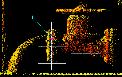
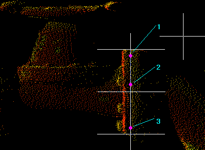
NEIGHBOR: It should be used whenever there is a good neighbouring pipe. The first pick defines the seed to grow a neighbouring pipe. The subsequent picks will adjust the flange work point along the axis.
-
EAST / NORTH / UP / VIEWX / VIEWY: If point clouds are registered such that the pipelines are pointing to east, north, or up, use fixed flange axis direction. If the view direction can be manipulated to make the flange axis parallel to the X or Y view direction, use the X or Y view direction. The first pick defines the seed point to grow a flange. The pick should be in a smooth area of the outer cylindrical surface of a flange. The subsequent picks will adjust the work point along the axis.
-
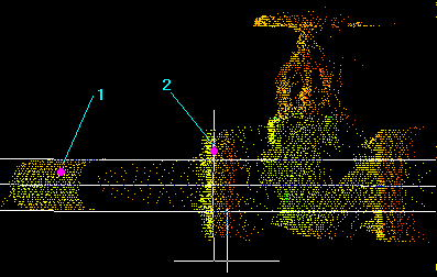
2POINT: The method is used when there are two flanges of the same diameter along the pipe. If the method is chosen, provide two pick points on two flange areas. The direction from the first to the second pick will be the flange axis direction. The subsequent picks will adjust the work point along the axis.
-
3POINT: Use this method only when other options are challenging to achieve. Align the view so that the flange axis is nearly parallel to the screen. Pick three points that can form a plane whose normal is the flange axis direction. A flange is grown from the first pick. The subsequent picks will adjust the work point along the axis.
-
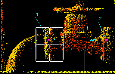
After the flange axis is determined, a flange illustrated by a cylinder and a circle representing the initial work point (flange insertion point) is displayed.
-
When prompted to pick a flange point, use the needed option to adjust the work point (the pick will be projected to the axis):
-
Reset: If the illustrated flange is incorrect, which can occur due to a faulty seed or algorithm failure, use this option to return and redo Step 2.
-
Offset: Enter axial offset of the desired work point from the pick. Typically, the back of the flange or exposed front edge of the flange is used as a reference. Next, pick a second point, and the work point will be adjusted using the given offset.
-
Flip: When the non-zero offset is used, CloudWorx will try to adjust the work point in an intelligent way. If the offset is to the opposite direction than expected, use this option to flip the offset.
-
-
When a flange work point is good enough, press ENTER to end the command. A circle and a line will be created to demonstrate the flange work point (see below).
When modelling a flange, the user can snap to the end of the line or the centre of the circle and use the line direction as the axis reference.