Create a scene
Five workflows produce scenes. The right choice depends on what you have and what you're trying to do.
|
You want to… |
Use this workflow |
|---|---|
|
Get a spatial overview of a project (when all assets are georeferenced on the same coordinate system) |
Scene from project |
|
Combine a known set of assets into one view |
Create new scene from selected assets |
|
Build a scene from scratch with full control over what's included |
Empty scene |
|
View two assets together when they aren't on the same coordinate system |
Visual comparison |
|
Quantify deviations between a design model and a point cloud |
Inspection |
Create a new scene from selected assets
-
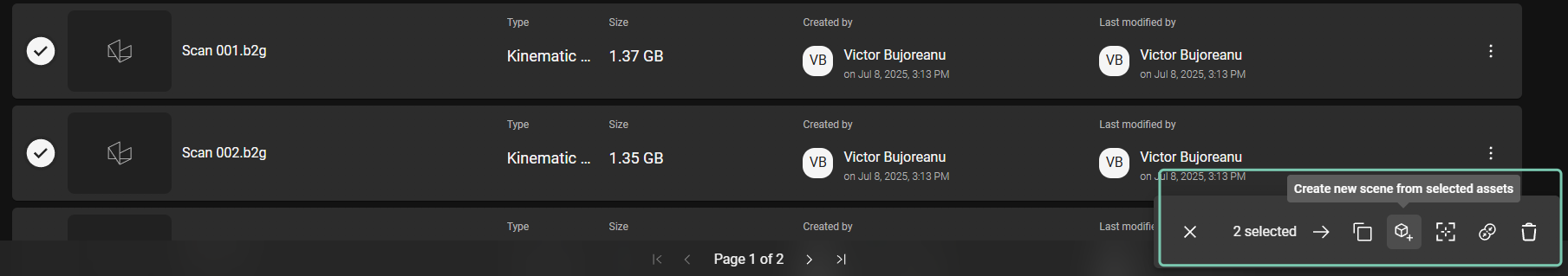
On the “Asset” tab, select the desired Assets to add to a scene.
-
In the context menu on the bottom right of the screen, locate and click the “Create new scene from selected assets” command.
-
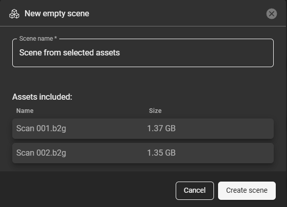
This will open a naming window that also shows the assets to be included in the scene. Click on “Create scene” to finish.
Coordinate behavior. Assets with explicit georeference metadata are placed at their actual coordinates. Assets with large local coordinates but no georeference metadata are grouped together and offset toward the scene origin, so the group is visible near (0, 0, 0). Measurements in the scene reflect the coordinates used in the scene, not the original file coordinates.
Create an empty scene
Useful for scenarios where you need full control over which data sets appear in the scene. Starting from an empty, you can add only the point clouds, meshes, or models relevant to the current task - for example, when preparing a focused view for a stakeholder review, isolating a specific project area, or working with a subset of data from a larger project.
Adding incomplete georeferenced assets to an empty scene
GeoCloud only treats a dataset as georeferenced if the georeference metadata is present in the file itself — for example, a .prj sidecar, internal WKT metadata, or an EPSG reference. Some datasets have large internal coordinates (typical of georeferenced data) but no explicit georeference. GeoCloud treats these as locally referenced, even though their coordinates suggest otherwise.
When a scene is created, its origin is set to (0, 0, 0).
-
If the scene is created with a georeferenced asset, the origin is placed at the rough location of that asset, and any non-referenced assets are positioned relative to it.
-
If no asset in the scene is georeferenced, the origin stays at (0, 0, 0).
A dataset that should have been georeferenced but is missing its metadata will be treated as non-referenced. Its large internal coordinates then place it very far from the scene origin, and it may be impossible to see in the scene canvas — the node is present in the tree, but the 3D view looks empty and Zoom to does not recover it.
Workaround
Bring the dataset closer to the scene origin. Two options:
-
Automatic — use the Create new scene from selected assets command. GeoCloud groups the selected assets and pulls them close to the origin based on their location.
-
Manual — apply a reverse transformation on the dataset to move it back toward (0, 0, 0).
The long-term fix is to ensure the source file includes valid georeference metadata before upload.
-
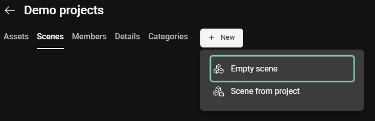
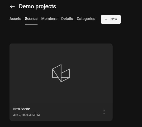
In the project view, go to Scenes tab and click the “New” button.
-
Click “Empty scene”.
-
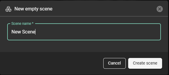
b. Name the scene and continue by clicking “Create scene”.
-
The newly created scene will be available in the “Scenes” tab.
-
To add data for visualization, open the scene, locate the drawer handle on the bottom of the page and open the drawer.
-
Select from the data sets available in the current project to add them to the scene.
-
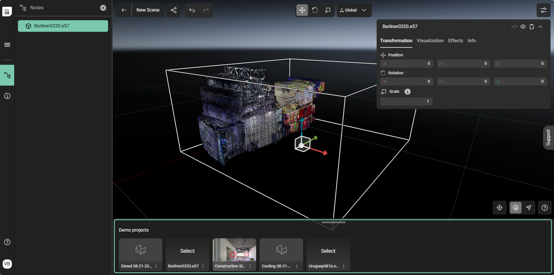
a.1 Alternatively, use “Add to origin” command to place the data set using its coordinates on the existing scene origin.
Coordinate behavior. Assets added via the Add to origin command from the drawer are placed at their actual file coordinates relative to the scene origin. See the panel above for what happens when an asset has large local coordinates but no recognized georeference metadata.
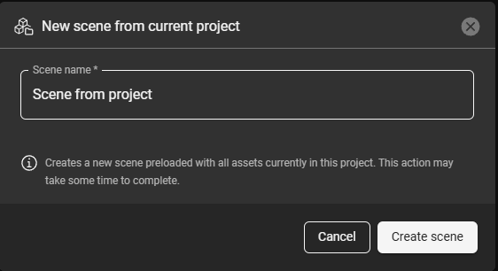
Use the “Scene from project” command
Using this command to create a scene from a project places all supported 3D data in the current project into a single scene. The data will be organized within the scene’s nodes (tree hierarchy) based on the folder structure of the project.
-
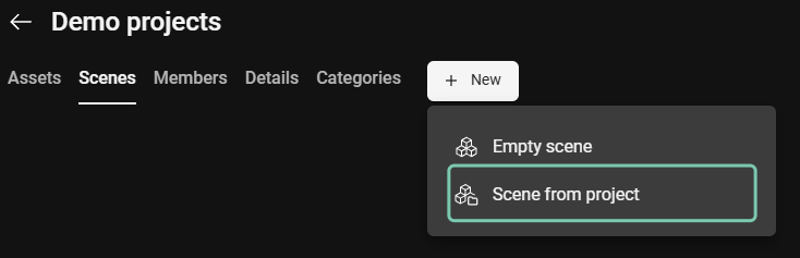
In the project view, go to the Scenes tab and click “New”.
-
Select “Scene from project”.
-
b. Name the scene and continue by clicking “Create scene”.
-
The newly created scene will contain a tree structure (nodes) based on the project folder structure.
Coordinate behavior. Assets are placed at their actual file coordinates. If all assets share a coordinate system at source, they line up correctly; if they don't, or if some assets lack recognized georeference metadata, they will appear misaligned or far apart.
For assets to line up in the scene, make sure they are georeferenced on the same coordinate system. Assets without recognized georeference metadata — including LGSx files, which scenes always treat as locally referenced — will not align with georeferenced ones. To align two assets that don't share recognized georeference metadata, use Visual comparison instead.
Create a visual comparison scene
Use this workflow when two assets need to be aligned before they can be viewed or analyzed together — for example, when one or both assets are not georeferenced on the same coordinate system. The guided workflow steps through point picking on both assets and produces an aligned two-asset scene.
Visual comparison is limited to two assets at a time. If the two assets are one point cloud and one model, the aligned scene can be used directly as the input for a deviation inspection.
See Creating a visual comparison scene for the full workflow.
Create an inspection scene
Use this workflow to quantify deviations between a design model and as-built reality capture. The inspection runs against exactly one point cloud and one model that are already aligned — either both georeferenced on the same coordinate system, or aligned via a visual comparison scene — and produces a mesh with deviation values mapped onto it.
Inspection parameters (exclusion zone, tolerance, mesh resolution) are set when the inspection is created, with recommended defaults for Wall, Floor, and MEP scenarios.
See Create an inspection for the full workflow.