autocad pro revit bricscad pro ultimate
Tools | Floor Flatness
Command Line
-
AutoCAD / BricsCAD: CWFLOOR
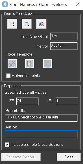
This command displays the Floor Flatness / Floor Levelness dialog, which enables the user to define a test area and then create a template to test for floor flatness and floor levelness.
The tool calculates the Floor Flatness and Floor Levelness values of a finished floor from point cloud data, according to the ASTM E1155 standard.
Using the Tool
To perform a Floor Flatness Analysis:
-
Click the Floor Flatness button in the Tools panel or type a command line prompt specific to the preferred CAD system and press ENTER.
-
The Floor Flatness / Floor Levelness dialog will open.
-
-
Define the test area:
-
Select Rectangle

-
Select Polygon

-
Select Clear

-
-
Specify the Test Area Offset and Interval values:
-
Test Area Offset: This parameter is used to exclude points that are too close to the fenced area to avoid their inclusion in the test area.
-
Interval: This parameter determines the spacing between sampled points that fall along the Run ID - Line. The default value is 1, which is the US standard.
-
-
Place the template:
-
Once the area has been fenced, select the desired Place Template option, then make two picks within the fenced area to define the first path of the test template.
-
The tool will extract a ground elevation every 1 foot down all four lines of the template.
-
Once the data is extracted, the results are computed, and a report can be generated.
-
-
Generate a report:
-
Specify the Overall Floor Flatness (FF) and Floor Levelness (FL) values, fill in the Report Title and Author fields, and click Generate Report. The report will be saved as a PDF file to the selected location.
-
Note: To replace the "Floor Flatness & Floor Levelness ASTME1155 FF & FL" image in the upper-left corner of the report, upload the desired image in the PNG format to the corresponding CloudWorx ProgramData folder, and rename it as FloorFlatnessLogo.png.