autocad pro
Fitters | Find Pipes
This command enables automated pipe extraction from classified point clouds, identifying straight pipe sections, elbows, reducers, and branches.

Using the Tool
To enable automated pipe extraction, follow the steps below:
Note: The first version of the Find Pipes tool requires data that has been automatically classified and has a classes for pipes and elbows at indexes 191 - Pipe Bend & 192 -Pipe Cylinder.
Cyclone 3DR and Hexagon GeoCloud, powered by HxDR, produce a compatible classification when using the plant model.
(Optional) Verifying that the Data Is Properly Classified
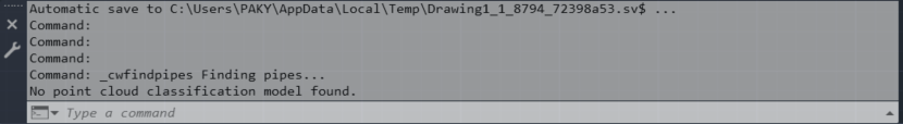
Note: If the data is not properly classified, a warning will appear in the command line.
-
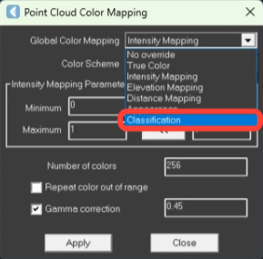
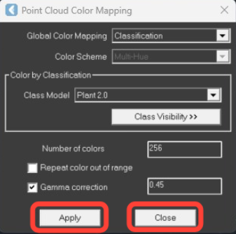
Navigate to Rendering | Color Mapping.
-
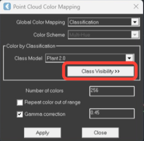
In the Point Cloud Color Mapping dialog, select Classification from the Global Color Mapping drop-down list and click Apply. The Class Visibility button should become active. Click it, and the Point Cloud Classifications dialog will open.
-
The Class Visibility button should become active. Click it, and the Point Cloud Classifications dialog will open.
-
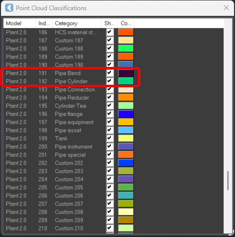
Scroll to index 191 & 192, labelled Pipe Bend & Pipe Cylinder, and deselect the check boxes. Inspect the point cloud to confirm that the pipe data disappeared, verifying proper classification. Select the check box again to restore the pipe data in the CAD window. Close the Point Cloud Classifications dialog.
-
Apply the changes in the Point Cloud Color Mapping dialog and then close it.
Using the Find Pipes Tool
-
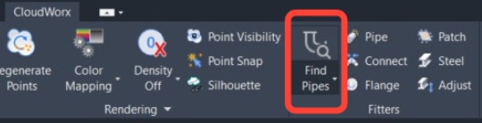
Go to Fitters and click Find Pipes.
-
In the Find Pipes dialog, adjust the filters* as necessary and click OK.
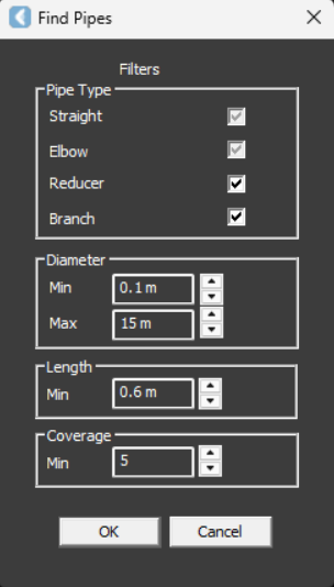
*The Find Pipes dialog opens with the following filters that help control the parameters of the created pipes:
-
Pipe Type: Allows to include or exclude the extraction of reducers and branches by selecting or deselecting the corresponding check boxes. The Straight and Elbow filters are greyed out, indicating that these elements are always extracted.
-
Diameter: Allows for a minimum and maximum diameter, ensuring that only pipes within a specified size range are identified and added to the project.
-
Length: The purpose of the length parameter is to prevent small, unconnected sections of pipes from being added to the project. This parameter controls the minimum length of the center line of a cumulative series of connected pipes found and added to the project. For example, in a series of connected pipes in a straight-elbow-straight-elbow series, individual elements may be shorter than the length parameter but as long as the center line of all of the connected pipes is greater than the length parameter, the pipes are added to the project.
-
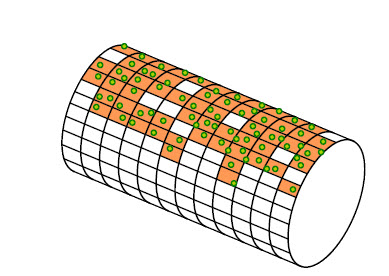
Coverage: Specifies the minimum ratio of surface coverage by points required to identify and add a pipe. This filter prevents creation of pipes with low certainty. For example, there may be an area of points where a pipe could fit. If the ratio of coverage of measured points compared to the theoretical pipe surface area is less than the filter setting, the pipe is not added to the project.
-
After automatic processing, the identified pipes will be displayed. Disable point visibility (Rendering | Point Visibility) to view the created geometry more clearly.
.png?cb=46e50585126c44eece06599fbe9d942b)