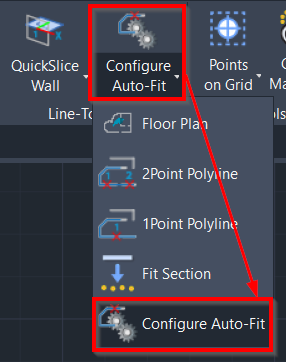
Configure Auto-Fit
AUTOCAD PRO REVIT BRICSCAD PRO ULTIMATE
Line-Tools | Configure Auto-Fit
Command Line
AutoCAD / BricsCAD: CWBFSETUP
This command allows adjusting settings for auto-fit polyline tools.

Using the Tool
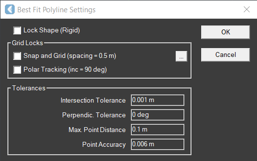
When the tool is activated, the Best Fit Polyline Settings dialog appears.

Adjust the settings as required:
Select the Lock Shape (Rigid) check box to adjust the position and orientation of the section without changing its shape.
Select the Snap and Grid check box to align the segments of the section to the Snap X spacing and Snap Y spacing of the current CAD Snap and Grid settings. The values for Angle, X base and Y base must be set to zero.
Select the Polar Tracking check box to align the segments of the section to the Increment angle of the current CAD Polar Tracking settings.
Notes:
Polar Tracking and Snap and Grid use the current UCS as a reference. The UCS must be aligned to the plane of the slice to use these options.
When the Polar Tracking or Snap and Grid check box is selected, CloudWorx applies the values of the current CAD settings even if these options are not enabled in CAD.
To change the current CAD settings, click the browse icon (…) at the right of the Grid Locks field.
Enter the preferred combination of tolerances:
Intersection Tolerance determines and maintains the connectivity of endpoints of open curves to other curves. If the endpoints are initially close to each other, use a smaller tolerance. Large tolerances may generate unexpected results.
Perpendicular Tolerance adjusts angular relationships between segments to be perpendicular or tangent if the error falls within the tolerance entered. Enter a value between 0.0 deg and 45.0 deg.
Max. Point Distance determines how far the points are from their ideal cloud points. Lines are not adjusted more than the value entered (the default is 0.1m or 20 times the RMS error); if this value is too large, it increases the uncertainty of the fitting results.
Point Accuracy displays the sampling error of the original point cloud.
