This step allows to extract steel elements from a point cloud. 3 types of steel elements are available: Beam, Column and Others.
All types of steel elements are characterized by the following:
Position: Low end position of the steel element.
Length: Length of the steel element.
A neutral axis: Line in a steel element that does not experience any stress during bending.
Axis: direction of the axis.
Axis position: 9 possible positions.
Shape type
I-Beam
T-Beam
Corner
Channel
Tube
Possible positions


5 shape types
Shape type
I-Beam
T-Beam
Corner
Channel
Tube
Representation


Standard reference example
W10x22
TB60
L8x6x1
MC10x33.6
HSS10x10x5/8
Hide / show the input cloud, levels, environment objects using the bulbs. Adjust the transparency of the input cloud using the slider.
You may also
 Filter the cloud according to its classes: see Auto Classification.
All previously extracted steel elements are displayed in the Extraction tree:
Steel elements are sorted by
 level and type (
 Column,
  Beam or
  Others )
You can Delete (DEL or via the contextual menu), Zoom on (via the contextual menu), Change color and Show/hide each on.
Toolbar
A toolbar is displayed in the scene to provide extraction, edition and copy tools for steel elements:
Selection tool
Use  Select to select a steel element.
Muti selection is available:
‘Ctrl' + Left Click: to add a steel element to the selection on click
‘Shift’ + Left Click + Drag: to add a bundle of steel elements with the square selection.
When a steel element is selected, its neutral axis is displayed.
Extraction tools
Use
Column, Beam or Others to extract the corresponding type of steel element:Select the Standard you want to use for the extraction.
Select Type to define the shape of the steel element.
For Column only
Force vertical: The neutral axis of the steel element is forced along Z direction.
Snap to levels: The steel element is stretched to nearest levels.
For Beam only
Force horizontal: The neutral axis of the steel element is forced to XY plane. The shape is also lays flat to XY plane.
For Others only
Constraint: See the table hereunder
Constraint | Description |
|---|---|
None | No constraint on the beam orientation |
Snap to axis | Element axis snapped to the closest local axis |
Snap to plane | Element axis snapped to the closest local plane |
Align to X | Element axis aligned to the closest local X axis. |
Align to Y | Element axis aligned to the closest local Y axis. |
Align to Z | Element axis aligned to the closest local Z axis. |
Orthogonal to X | Element axis orthogonal to the local X axis (in the plane). |
Orthogonal to Y | Element axis orthogonal to the local Y axis (in the plane). |
Orthogonal to Z | Element axis orthogonal to the local Z axis (in the plane). |
Alignment tool
Use  Alignment to join a steel element to 2 reference elements.
Duplicate tool
Use  Duplicate to create copy of existing steel elements.
Extracting
Use the https://hexagon.atlassian.net/wiki/spaces/RCD/pages/46401782038/Steel+Extraction#Extraction-tools from the toolbar to perform an extraction.
Extraction view
An additional scene called Extraction view is displayed when an extraction is performed.
Extraction view displays profile view of the extraction along the profile characteristics.
Information related to the extraction is displayed on top left of the Extraction view.
This information is not updated when the reference is changed manually.
Free move
Use Free move’s manipulator to manually adjust the position of the steel element.
In the Extraction view, the adjustments are done in profile’s plane.
In the 3D view, the adjustments can be realized freely.
Profile
In Properties, change the reference if needed.
References are sorted in ascending order, from the smallest Overall error to the highest.
Overall error shows the overall quality of the fit between the section and the point cloud.
Coverage shows the percentage of profile area which overlaps the point cloud.
When a reference is selected, it is automatically applied to the steel element.
You may filter the references by name using Search Reference.
The results depend on the selected standard.
Element edition
Use https://hexagon.atlassian.net/wiki/spaces/RCD/pages/46401782038/Steel+Extraction#Selection-tool or the extraction’s treeview to allow edition of the steel element.
General
In Properties,
Edit the Level the steel element is assigned to.
Edit the Axis position of the steel element.
The Axis position is defined relative to the axis direction. As a result, the visual representation of the neutral axis in the 3D scene may differ from the Axis position label.
Profile
In Properties, change the Reference of the steel element.
Overall error and Coverage values are not saved after the extraction.
Only available when only one steel element is selected.
3D scene
Edit the length by using the handles placed on each extremity of the steel element.
Quick mode: Grab and release the handles for an approximate adjustment.
Precise mode: Click on the handle to adjust with Define Points.
While in Quick mode or Precise mode, use TAB to enter numerical values.
Tips & Tricks
Only the visible points are used for extraction: hide the unwanted classes to take full advantage of the point cloud Classification.
Tips & Tricks
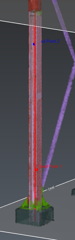
To get an efficient profile extraction, select an area where only the points from the point cloud define the steel element (not too close from an intersection like a floor or a connection (see 3D scene - Example 1).
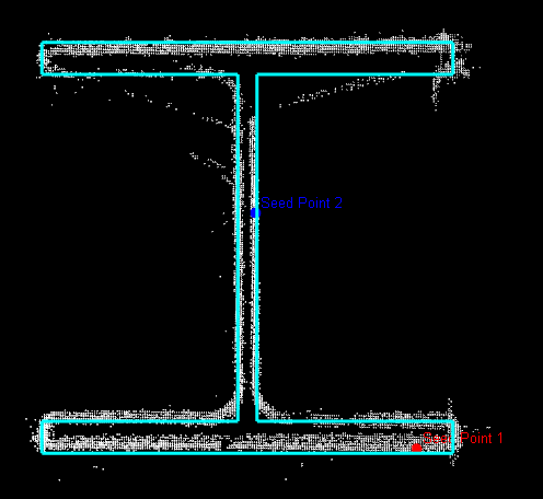
In 2 points extraction, select 2 different parts of the profile (see Extraction view - Example 2: a point on the flange & a point on the web)
3D Scene - Example 1
Extraction view - Example 2
Practice