Though many links will be created during the import process, adding additional links will strengthen and improve the overall quality of registration.
Cyclone REGISTER 360 PLUS will suggest appropriate links to the user, and they can be accepted or rejected based on the needs of the project.
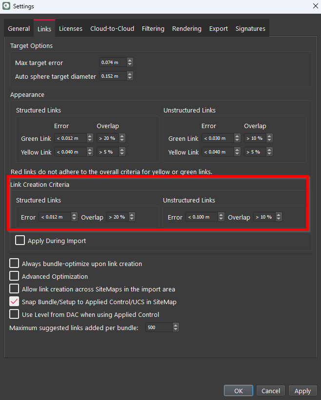
Users can set link creation criteria in Settings to guide Cyclone REGISTER 360 PLUS in automatically creating links.
Most of the selection methods are only available in the SiteMap view. Existing links can be updated in the Bundle Cloud view, but suggested links are only available in the SiteMap view.
Selecting Setups with the Fence Select Tool in the SiteMap View
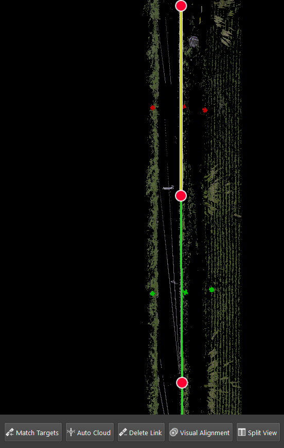
From the top toolbar, select the Fence Setup icon and select the type of fence selection: rectangular, circular, or polygon. Draw a fence around the Setups to be joined. Once selected, an action bar will appear at the bottom of the screen and show the options available to join the selected Setups. Selecting Setups will allow the use of Visual Alignment, Split View (3 picks), Auto Cloud, or Target Matching. The user can also delete a link and Setups from the action bar.
Using Suggested Links or Existing Links in the SiteMap View
In the SiteMap view, select a Bundle or Setup and move it within proximity to another Bundle or Setup. When the Show Suggested Links Within Bundle / Show Suggested Links option is selected from the context menu of the selected Bundle or Setup, up to 5,000 suggested links will appear.
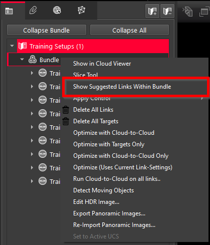
Select a suggested link (dotting white line) to bring up the action bar at the bottom of the screen with the options to join Setups. Or select an existing link (red, yellow, or green) to bring up the action bar to join or re-align the link.
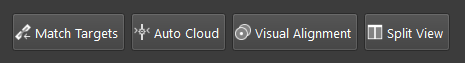
Auto Cloud
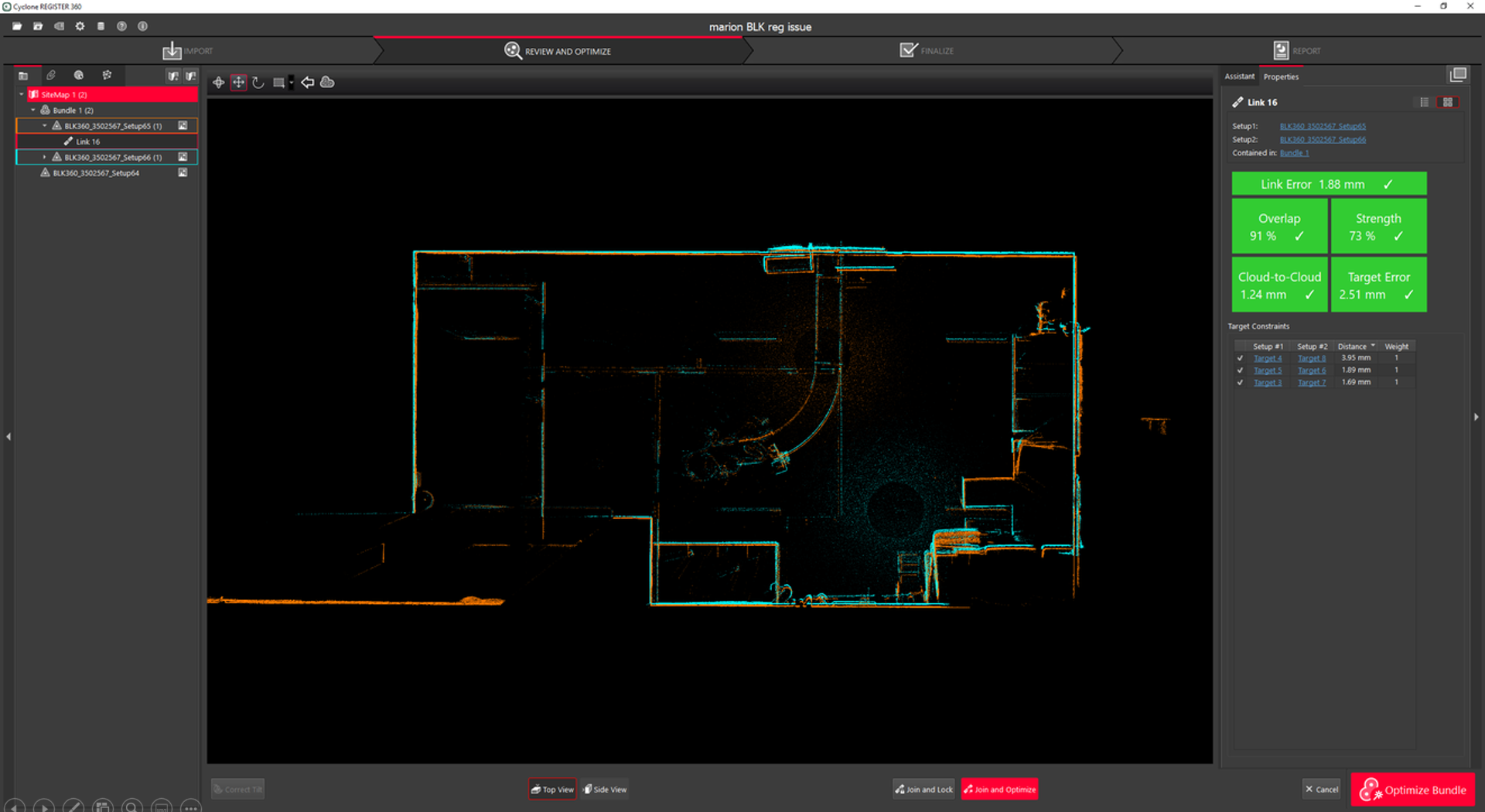
Automatically aligns selected Setups and creates links using the geometry of the point clouds. The example in the image below shows the selection of a suggested link with the option of joining with Auto Cloud.
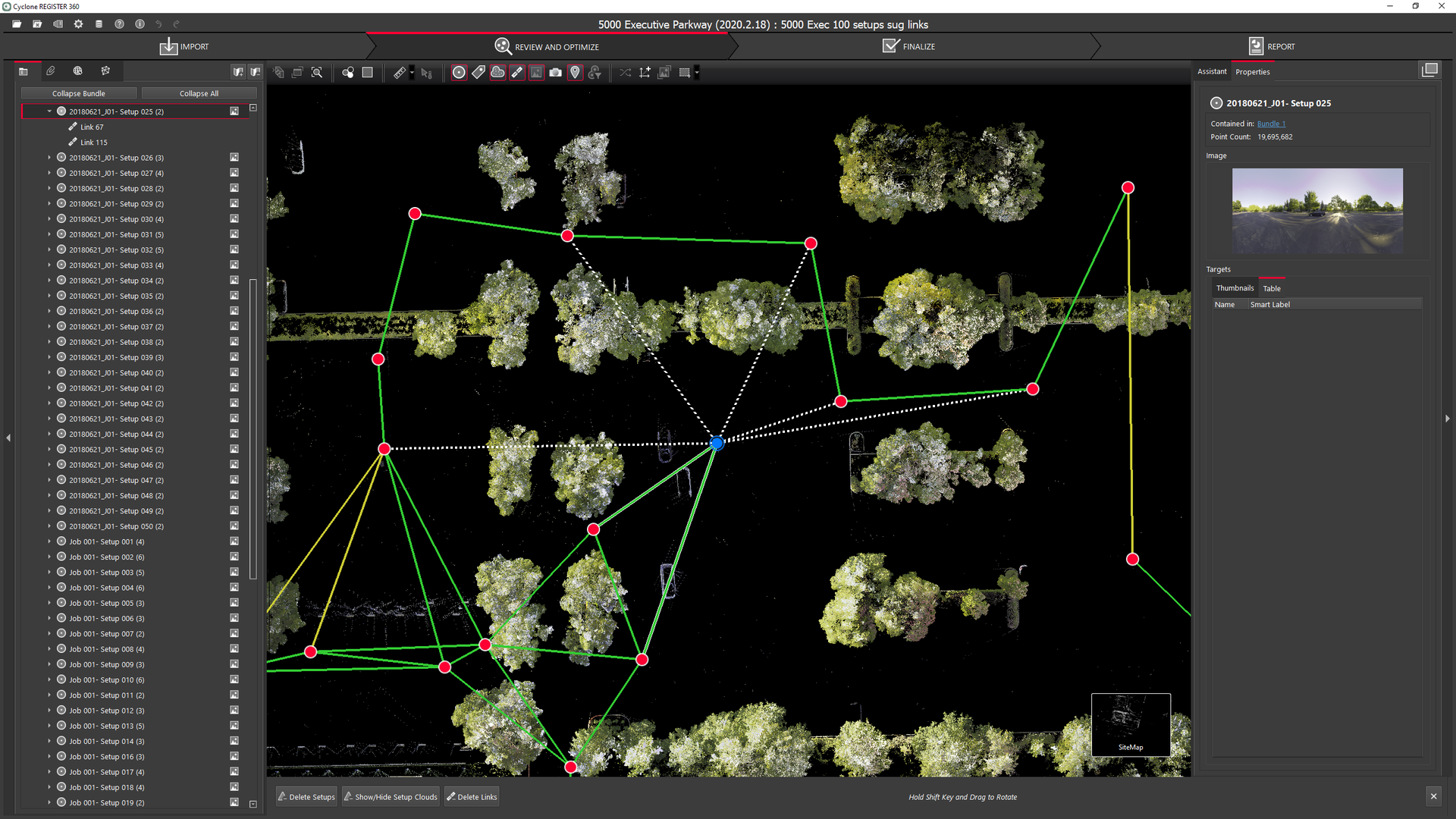
To better assess the link quality, in Settings, users can add the maximum error and Cloud-to-Cloud overlap percentage for green, yellow, and red links. Both error and overlap must be within users' settings to satisfy the condition for any given colour.
Match Targets
Automatically aligns the selected Setups using the geometry of the targets in those Setups.
In Settings | Links, users can check the Max target error option and set the maximum amount of error allowed when forming links.
Note: Three targets are required between each Setup to run target matching.
Targets can be represented in two colours: green or red. The colour indicates whether the target is being used in a link. Once the match is made, the target vertex changes from red to green.
Note: To remove a target that is already in use (the green one), it’s necessary to remove the link first.
Visual Alignment
Shows separate Setups in different colours so that the user can align them manually. See the video by entering Visual Alignment and clicking the Assistant tab. A full explanation of the functionality is shown.
In version 2025.0.0, the Cloud-to-Cloud cloud is always the default cloud, which does not reflect any filtering done by the settings under Settings > Cloud-to-Cloud. However, the mathematical calculations correctly take these settings into consideration.
-
Tilt correction inside of Visual Alignment
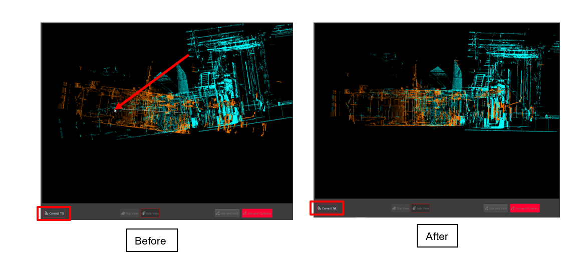
Users can now use Visual Alignment on tilted Setups. The tool allows the user to correct the tilt of Setups manually to enable Visual Alignment. This tool does not level the Setups and can only make the Setups level enough to enable Visual Alignment. The corrected tilt is carried through to the coordinate system of both Setups.
-
To use this tool, enter Visual Alignment, then enter the Side View, and click the Correct Tilt button. Use the Rotate Cloud option to level each scan. Hold down the Shift key to rotate the orange scan.
Note: Leveled scans from the P-Series and C-Series scanners are not adjusted when using tilt correction, as the internal compensator holds an upright direction.
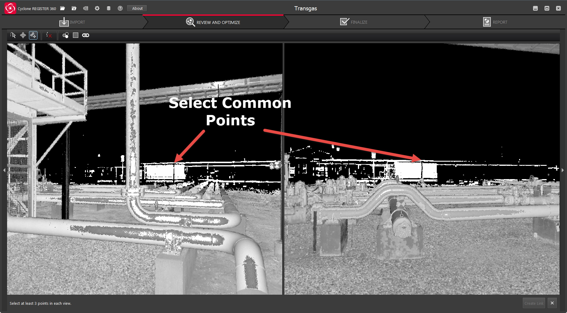
Split View
The Split view represents the view from two different Setup locations on the same SiteMap. The user selects matching points in each view to create links. At least 3 matching picks are needed to form a link (3 picks in one Setup and 3 picks in the other). If the geometry of the picks does not match, then the option to create a link will not be shown.