In this exercise, we will see how to unfold a building in order to generate one orthoimage for all its frontages. Note this workflow can be also used for rounded shapes.
Open the file FrontageOrthoImage.3dr.
Draw the polyline path
Select the cloud and launch Scan To Plan. Define a horizontal slice: for instance at Z=199.5m using the Advanced mode. Move to the second step and draw the building contour in a simplified way.
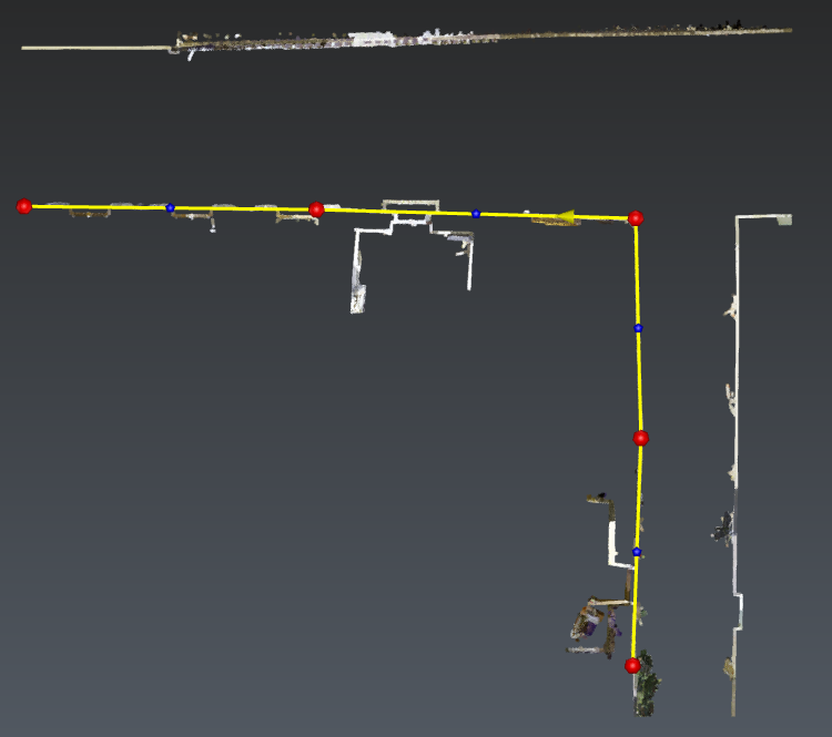
Pay attention, the path has to be drawn counter clock wisely. This can be directly modified by selecting the polyline and clicking the reverse button. Exit the workflow. Here you can extend the polyline by snapping the edge: double click the polyline to edit it, it will stay planar.
Draw polyline can also be used rather than Scan To Plan : snap directly to corners. If a corner is not visible, you can pick the edge at any elevation instead since the path elevation is not taken into account by the unfold command. However Scan To Plan is easier to use when edges cannot be identified like this case.
Unfold the cloud
Select the entire cloud and the path polyline. Then launch Unfold Cloud. The axis direction is by default set to Z=1: keep this setting (the vertical will stay vertical after unfolding).
Choose to sub-select the points to unfold by using the Slice selection option. This is particularly helpful to unfold only objects which are next to the frontage. For instance, set the Right width to 0.75m and click Preview the selection.
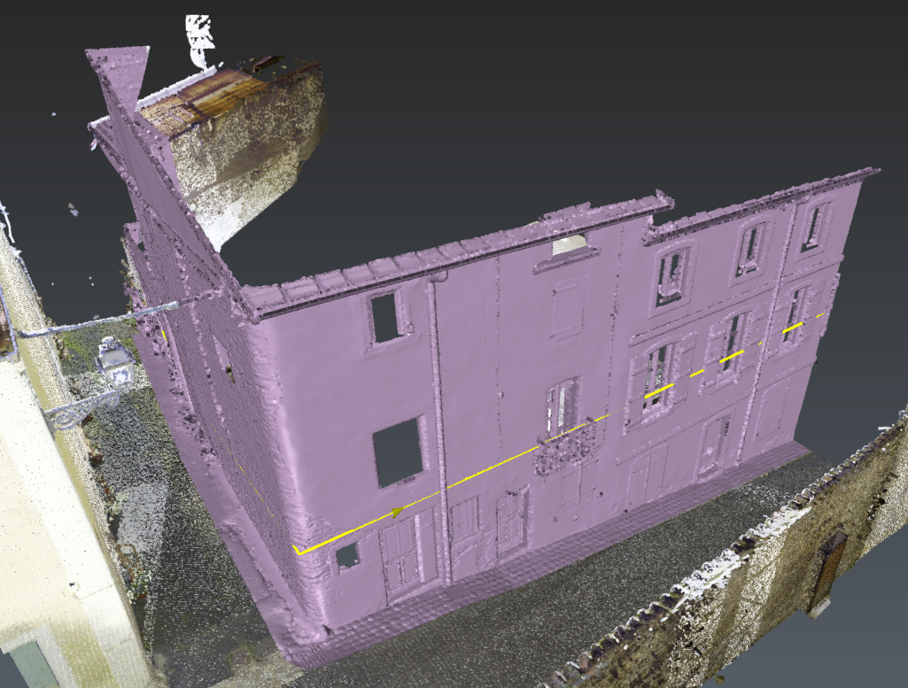
Finally, click Preview and OK. The view switches to Front ortho.
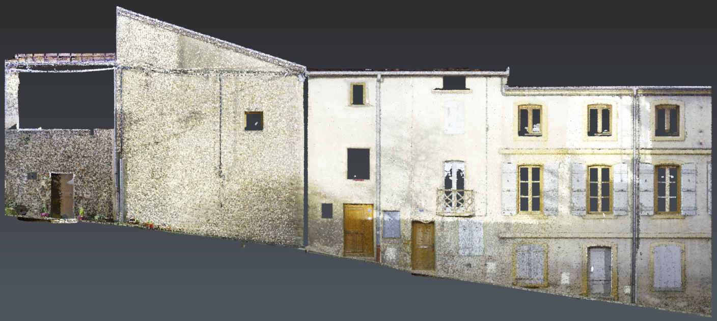
This result can be used to generate an orthoimage. Optionally you can keep this result and continue with Exercise: create an ortho-image and import it in AutoCAD .