This guide covers the Floor Plan tool, illustrating its capabilities through a practical workflow example in Revit.
Practice data
Initial Preparations
Importing Project Data
-
Import the project data.
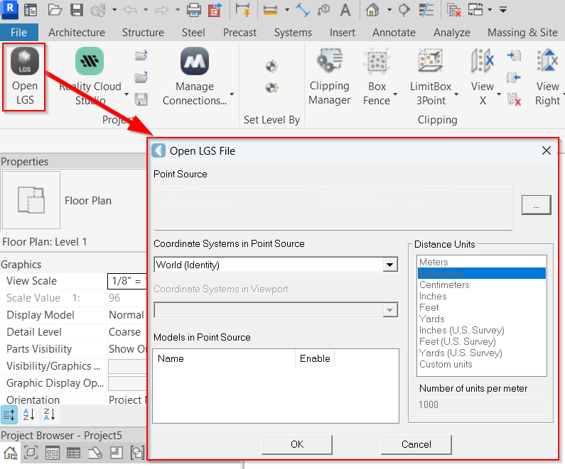
Note: BLK360 data is saved as the LGSx file. If your data is stored in a different format, please choose the appropriate import option. Refer to Connect To Help section for more details.
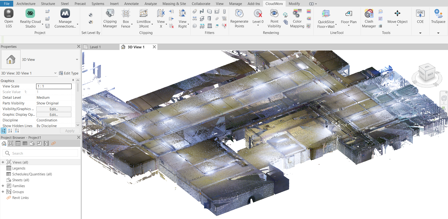
1.1. In the Project panel, click Open LGS File and browse to the required file.
1.2. Position the imported model as necessary using the navigation wheel.
Setting Up Levels
In Revit, setting up levels is crucial for attaching elements at specific heights to ensure they are accurately visualized in the 3D view. As we move forward with creating a floor plan, it is essential to establish both ceiling and floor levels.
-
Go to the Set Level By panel and click Point.
-
Pick a point on the cloud.
-
In the Set Level dialog, enter the level name and specify where to save the associated plan view in Revit Project Browser. Click OK.
-
Rotate the model to find the floor and repeat Steps 2-4 to set the floor level.
Tip: To prevent confusion with the levels available in Revit’s Project Browser, consider deleting unnecessary levels and retaining only those you’ve just created.
Creating Quick Slice
To speed up processing of point cloud data, it can be helpful to temporarily hide unnecessary points. By eliminating specific portions of data, you can focus on the area of interest and avoid unintentionally selecting points outside of it. Additionally, setting up a quick slice is essential before utilizing the polyline tools available in the Floor Plan tool. See QuickSlice for more details.
-
Create a quick slice to clearly view the point cloud data you'll be working with in a Floor Plan tool.
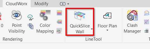
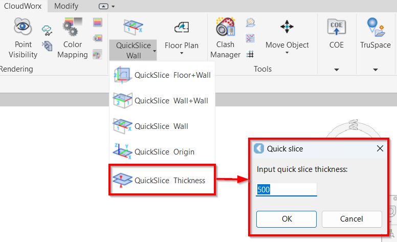
6.1. Navigate to the LineTool panel, and choose the appropriate QuickSlice creation method. In this workflow, the QuickSlice Wall option is selected.
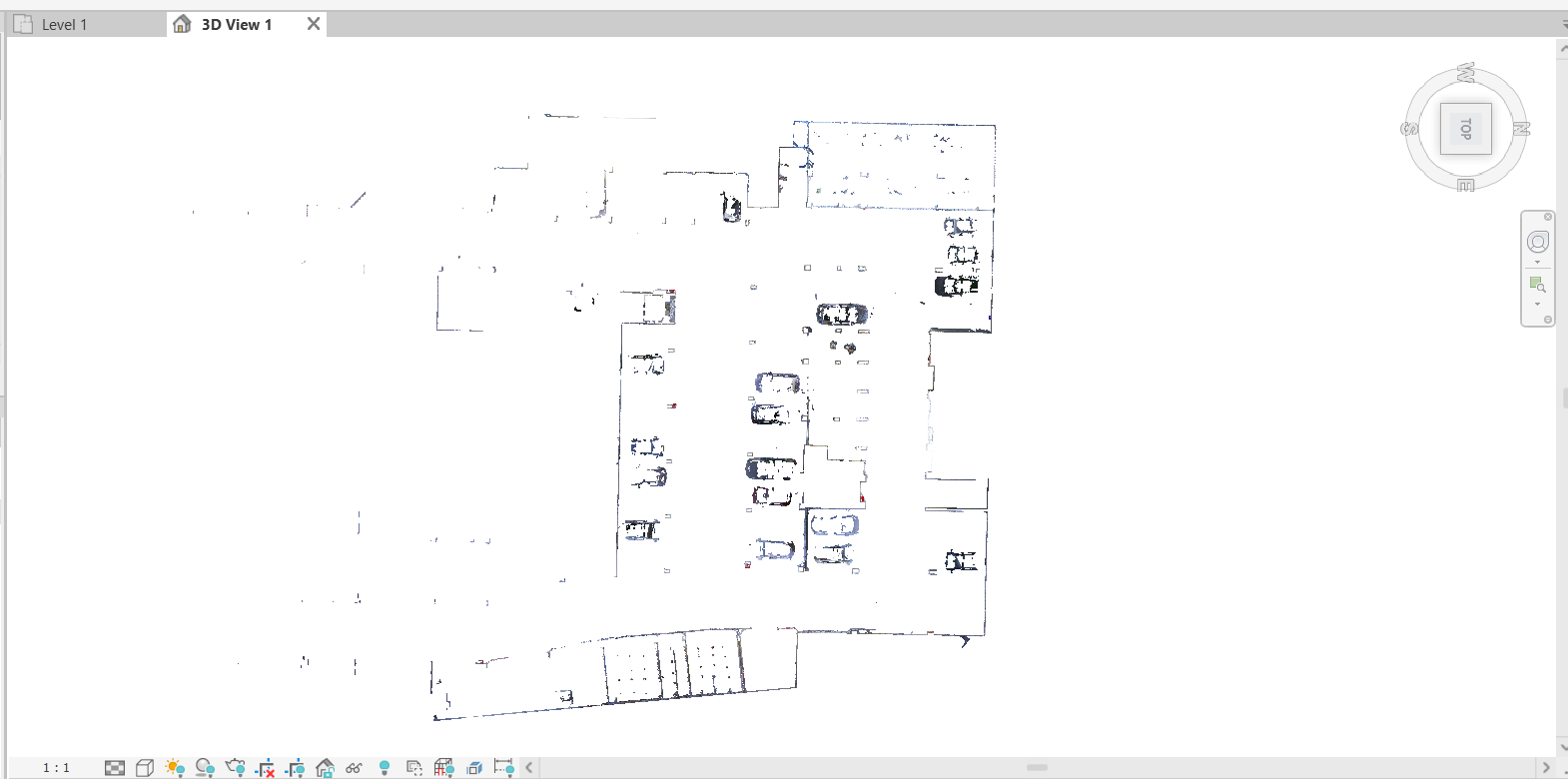
6.2. Rotate the point cloud to identify the desired wall and pick a point on it. Once clicked, the slice will be created and automatically oriented to the TOP view.
6.3. If you want to change the slice thickness, navigate to LineTool | QuickSlice Thickness. In the Quick slice dialog, enter the preferred thickness of the slice.
The default thickness is 5 meters. In some cases, it may be helpful to change thickness to create a thinner slice, which can enhance the clarity of the lines. Additionally, if the wall is tilted, adjusting the thickness can make the center of the wall less ambiguous.
Note: The slice thickness can also be adjusted in the Floor Plan tool using a slider (see Step 9).
-
(Optional) To achieve higher contrast with the background and improve point visibility, you may change the color mapping as follows:
7.1. On the Rendering tab, click Color Mapping.
7.2. In the Point Cloud Color Mapping dialog, select Appearance from the Global Color Mapping drop-down list.
7.3. Select the desired color and click Apply.
Using Floor Plan Tool
-
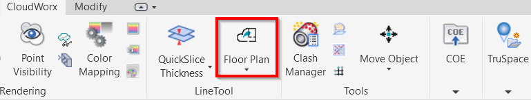
Go to the LineTool panel and click Floor Plan. The Floor Plan tool will open in a separate window.
-
Adjust the thickness and position of the slice along the Z-axis by using the slider on the left.
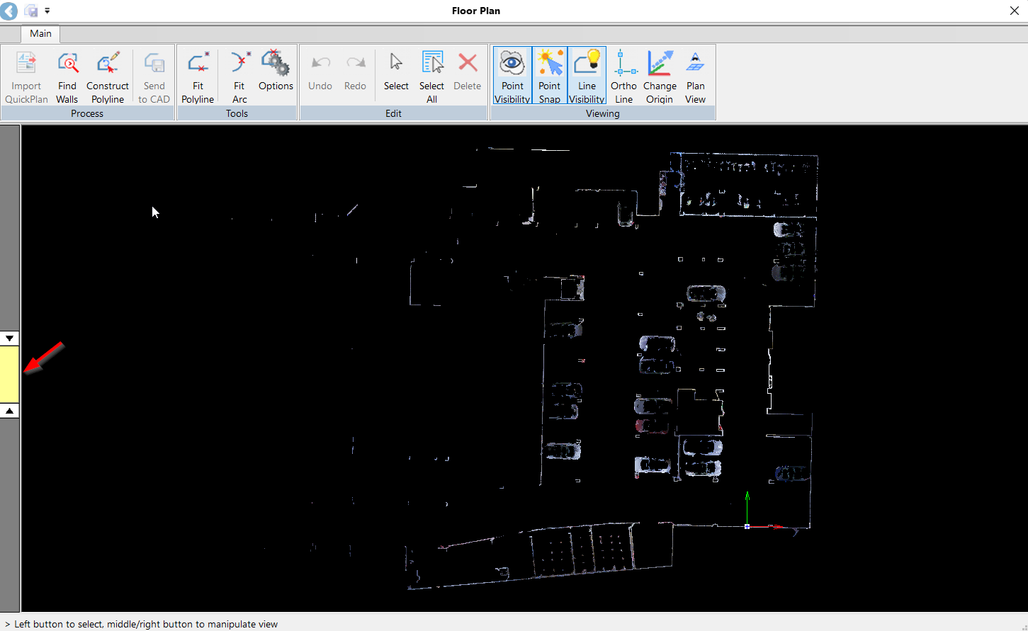
Tip: For better navigation within the selected tools, refer to the hints located in the lower-left corner of the Floor Plan tool.
Creating Preliminary Floor Plan
-
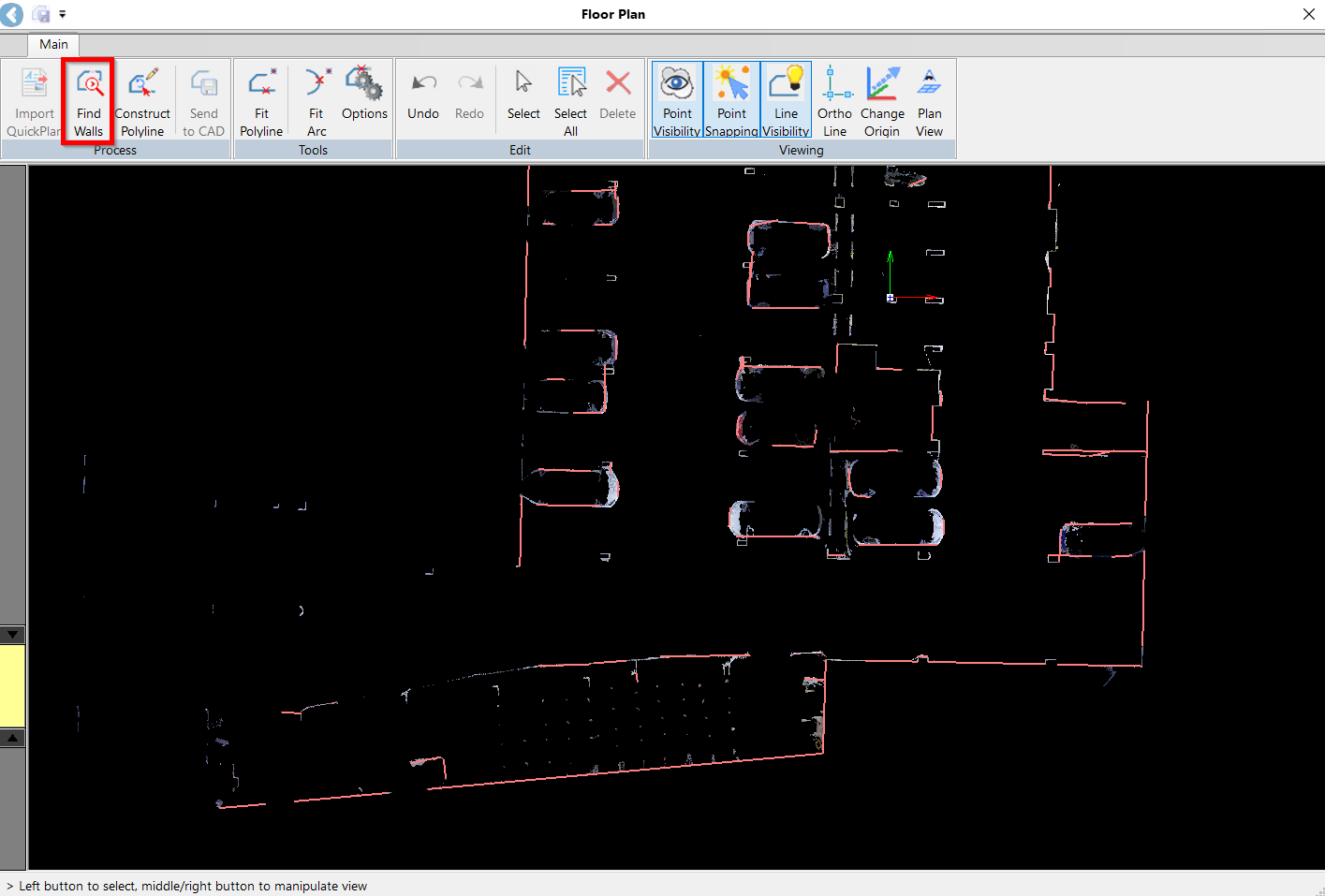
To automatically generate a preliminary floor plan, use the Find Walls tool in the Process panel. The Floor Plan tool will identify all possible line segments and display them as red lines.
-
Verify the suggested line segments and connect them in a polyline. The Floor Plan Tool offers a combination of Automated, Semi-Automated, and Manual options for completing a drawing.
11.1. Automatic
In the Process panel, click the Construct Polyline tool to enable line drawing. If you are satisfied with the suggested line, click on it, and it will turn yellow, indicating that it has been verified and approved. Repeat this step for other properly extracted line segments.
11.2. Semi-Automatic
If you need to adjust the angle of two line segments, enable the Ortho Line tool in the Viewing panel. Simply select the line you want to adjust and the tool will try to adjust the selected line as close to the angle as possible.
.gif?cb=8fc9c549b495c5d4299918e4fbd414ca)
To adjust the polyline alignment with the point cloud, click on the endpoint of the line segment or the vertex of the lines. Then, drag it to the desired position. The selected lines will turn violet, indicating they are editable.
Tip: Turn off point snapping (Viewing | Point Snap) to avoid accidentally selecting unwanted line segments.
11.3. Manual
In areas with complex wall structures where the line is partially detected, you can draw the line manually. Click on the line at the starting point, drag it in the desired direction, and release the mouse at the endpoint. The tool will attempt to draw line segments.
Saving Created Polylines
-
After the polyline is adjusted and appears as a green line, click Send to CAD.
-
In the Polyline to Wall dialog, specify the following settings:
13.1. In the Select Level field, choose the level you created earlier to which the feature should be attached.
13.2. In the Top constraint field, choose the level to which the feature's height will be adjusted automatically. If you select the Unconnected option, you will need to specify the Wall Height manually.
13.3. Select the Wall Type from the drop-down list.
13.4. In the Wall Location field, specify the direction in which the lines were drawn.
13.5. Click OK to send the polyline to CAD.
Tip: For optimal results, position the Floor Plan tool and your CAD window on separate screens. This will allow you to verify the linework immediately as it is sent from the Floor Plan tool to CAD.
Refining Floor Plan
After making full use of the preliminary Floor Plan tools, you may wish to refine the Floor Plan further by extracting additional polylines.
Fitting Polylines
-
Sometimes, low point cloud density will make automatic line extraction difficult. In this case, use the Fit Polyline tool in the Tools panel to create lines in areas where the lines haven’t been extracted automatically:
14.1. Click on each line representing a structure that needs to be drawn. The lines will be generated and highlighted in yellow.
14.2. Click Close Polyline to complete the drawing of a polyline. After the polyline is closed, all lines forming a structure will turn green.
14.3. Adjust the lines to ensure they fit the structure properly.
14.4. Click Send to CAD in the Process panel to save the polyline.
Fitting Arcs
-
To draw structures with rounded edges—for example, columns, staircases, and so on—use the Fit Arc tool in the Tools panel:
15.1. Specify the starting point and endpoint of the arc. The arc will be created.
15.2. To adjust the arc, click the polyline again and make the necessary adjustments.
Tip: When data noise results in an unclear line, disable point visibility to refine the finish line more effectively. The Floor Plan tool simplifies the process of adjusting the fit of a finished line, even under less than ideal conditions.
15.3. Click Send to CAD to save the created arc on the CAD drawing.
Reviewing Created Floor Plan
-
After completing your drawing in the Floor Plan Tool, close it and view the result in the Revit view.
Note: When you exit the Floor Plan tool, unapproved red lines will be discarded.
The created wall will appear with its inside face aligned to the drawn line.