Create an Inspection
Project Members with Roles: Admin or Collaborators can create a Scene with a scan-vs-BIM deviation inspection between two Assets. The Inspection shows the results of the deviation analysis between the planned vs. as-built conditions.
Overview of the Inspection tool
The prerequisites for creating an Inspection are:
The two Assets are one (1) point cloud (LAS, E57, LGSx, B2G) and one (1) model (IFC, RVT).
The two Assets are aligned
If both Assets are georeferenced on the same user-defined coordinate system (UCS), no manual effort is required first. If only one or neither of the Assets is georeferenced, follow the guided workflow to align them together: Creating a visual comparison scene.
Create a New Inspection
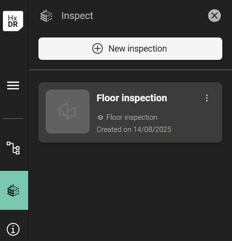
A tab is available on the navigation bar - “Inspect”:
.png?inst-v=189e9461-c622-4ec9-8b74-6359680d1bc4)
“New inspection” command
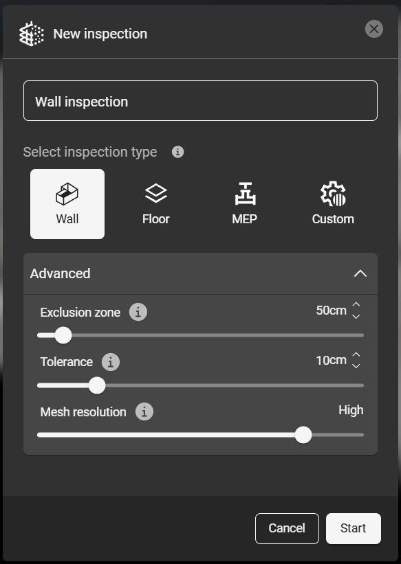
Clicking “New inspection” command will open the dialog. Give the inspection a name.
Choose your inspection parameters and click “Start”. There are recommended default parameters for Wall, Floor, and MEP scenarios, as well as a Custom setting. The advanced parameters can be adjusted manually:
Exclusion Zone - Points outside this range will be excluded from the inspection analysis to eliminate potential errors.
Tolerance - The acceptable range of deviation between the design model (BIM) and the as-built conditions (point cloud). The Tolerance can also be adjusted dynamically when viewing the analysis' results.
Mesh Resolution - the level of detail and precision of the triangulated mesh. A high-resolution mesh may not yield more detailed results, but it will be slower to load (render), navigate, and so on, due to the large number of polygons, which may not be necessary.
Note: The Exclusion Zone and Mesh Resolution parameters are permanent settings for each individual inspection. To change these values after an Inspection analysis is complete, a new Inspection must be made.
However, the Tolerance parameter can be edited dynamically while viewing the Inspection results. Deviation values are mapped to the resulting mesh based, but the colors representing the deviation values are not textured onto the mesh directly.
The resulting Inspection will automatically open in the Scene view when the analysis is complete. The deviation values are mapped onto the new mesh.
Hover the mouse over the Inspection mesh, and the quantified deviation value is displayed (you may need to turn this on in the Aligned Group’s Effects settings.
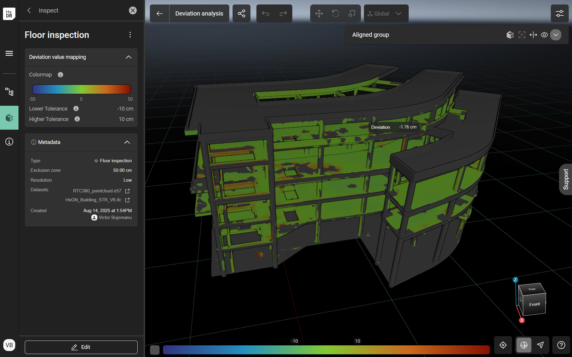
Values of the deviation are mapped on the model
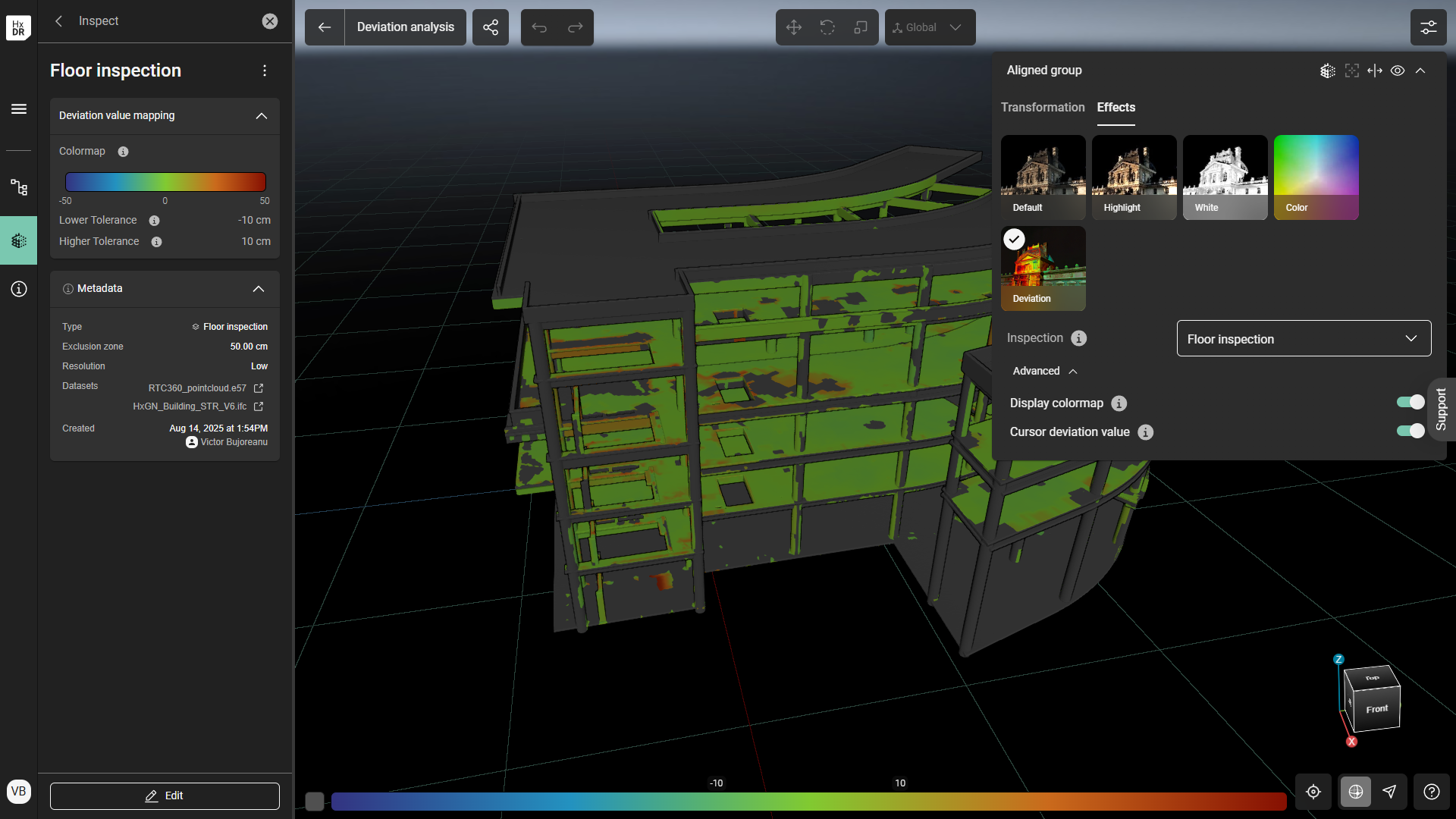
Toggle “Display colormap” and “Cursor deviation value” in the Aligned group → Effects
OPTIONAL: Select “Edit” at the bottom of the left sidebar to adjust the Tolerance values and their colormap style (if desired). The values can be adjusted with the slider(s) on the color map bar or by editing the text values in the text fields.
For the colormap, choose between “Gradient”, “Over/Under” or “Range” styles.
Gradient is the default mode and allows the user to adjust the Lower and Higher Tolerances (where the default lower and higher thresholds use the Tolerance parameter from Step 3 as a plus/minus range; i.e., if in Step 3 “10 cm” is selected as the Tolerance, the lower tolerance value will be -10 cm and the higher tolerance value will be +10 cm).
Over/Under sets a Threshold value within the Exclusion Zone range. The Threshold is a single value at which all deviations are considered notable for tagging/investigation/etc. If used, this value should be chosen based on the Project requirements; for example, deviations over 5 cm in the positive direction are the only ones to be investigated, in which case the Threshold could be set as +5 cm.
Range sets the Lower and Higher Tolerances, similar to Gradient. However, values outside the range will receive an absolute interpretation, being either under or over the Tolerance without a gradient.
Deviation values mapping options: Gradient, Over/Under, Range.
The saved Inspection can also be found at any time by choosing the Inspect tab from the left navigation bar.