Exercise overview
In this exercise, we see how to unfold the point cloud which can make easier to spot defects and equipment. The Survey and AEC license are required for these computations.
Several steps are included in this exercise, involving the following commands:
The file used in this tutorial is TunnelExtraction.3dr (see Extract a tunnel mesh ).
Overview
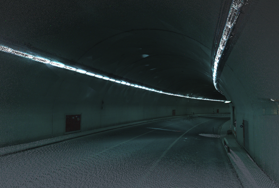
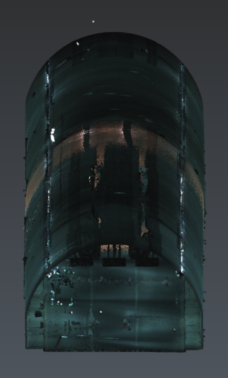
The file contains the point cloud of a tunnel. The cloud is displayed here in the Real Color representation mode, as each point was measured with colors. Nevertheless, the tunnel is rather dark; this is why you can change the representation mode if necessary.
Unfold around Z
Show only the Tunnel cloud, select it and launch Scan to Plan.
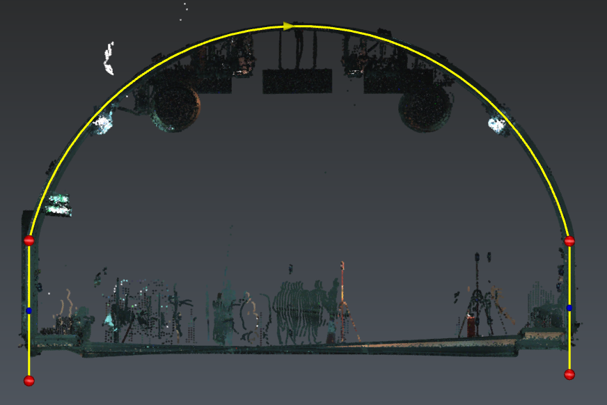
Set the slice to Z mode and define a very large Thickness to keep all points (50m). Then click on the cloud and go to the next step.
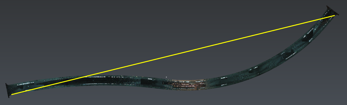
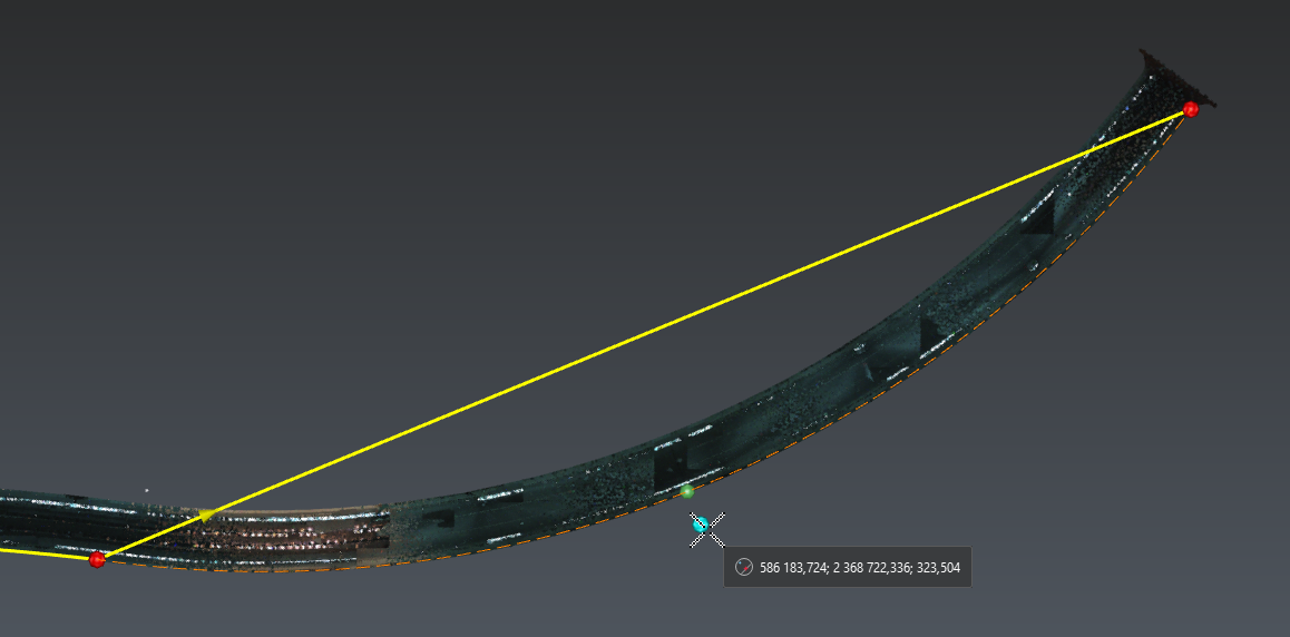
Now, draw manually the left and right sides:
-
Activate only the Nearest snapping mode.
-
Click the extremities (from west to east).
-
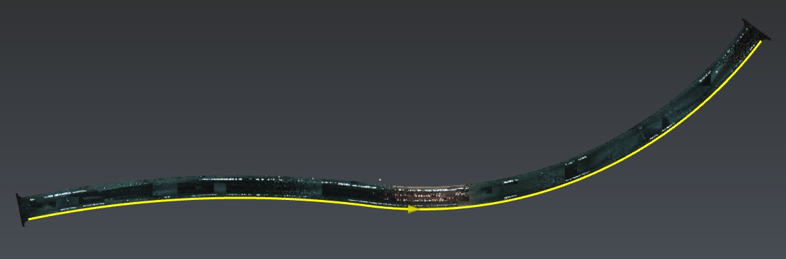
Insert the inflexion point.
-
Then edit the polyline: insert 2 arcs between the 3 vertices.
-
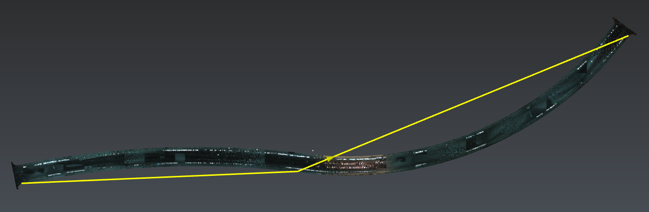
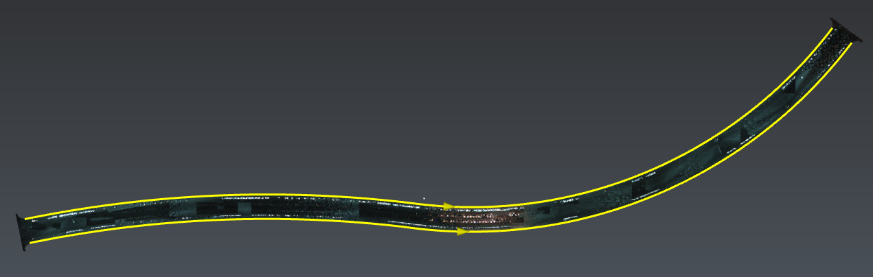
Repeat for the other side.
-
Ensure that both polylines are oriented towards the east. If not, reverse them.
This step must be carried out carefully, otherwise the final result may be very inaccurate. If you think your inflexion point was not precise enough: select all intermediary points, press DEL and insert again the inflexion point.
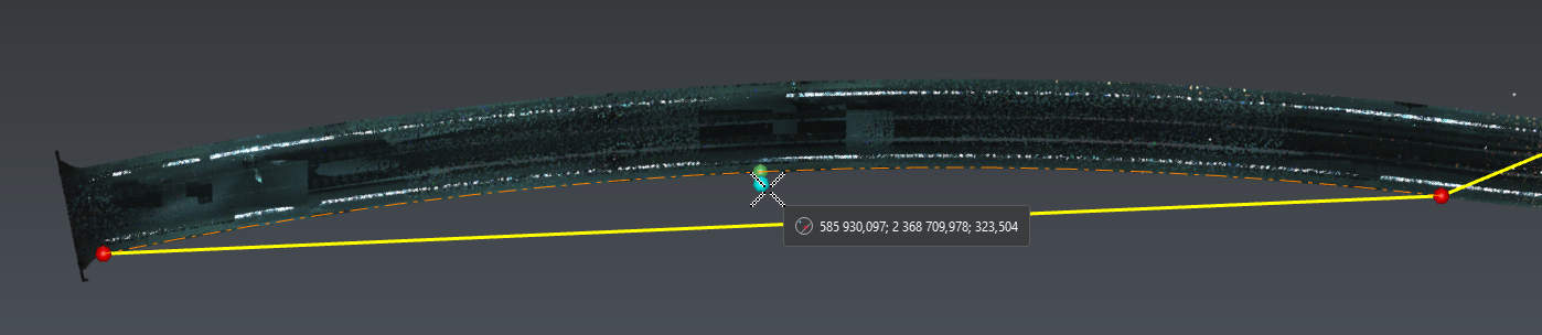
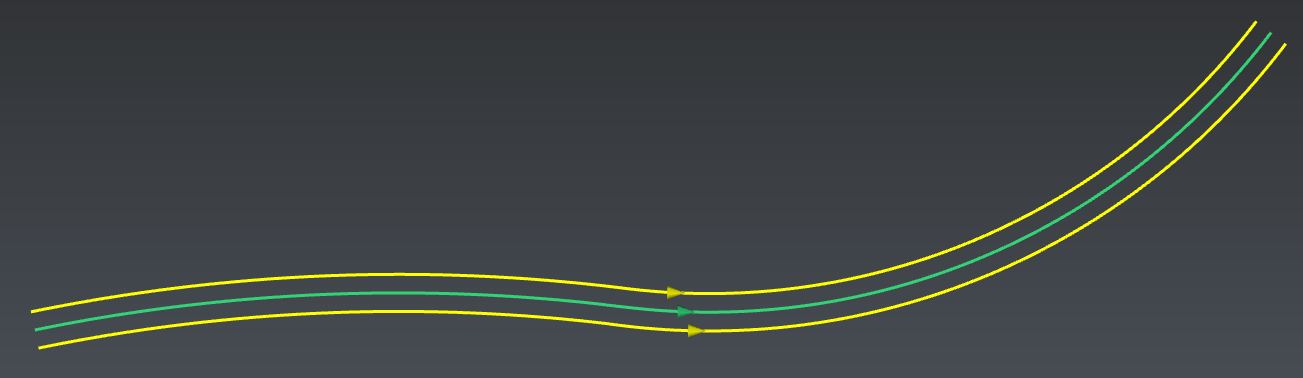
Exit the workflow, select both polylines and launch Median line :
Select the Tunnel cloud and the median line, then launch Unfold Cloud.
Let the axis to Z=1 and unfold All points. Validate the command.
Unfold around Y
Show only the Tunnel cloud_unfolded, select it and launch Scan to Plan.
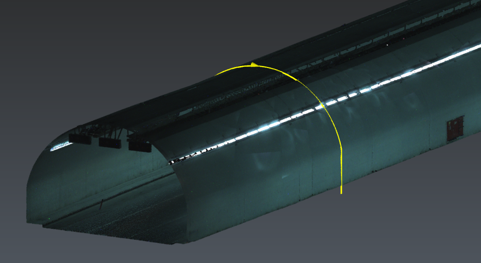
Set the slice to -Y mode (only available in Advanced mode) and set a very large Thickness to keep all points (50m). Then click on the cloud and go to the next step.
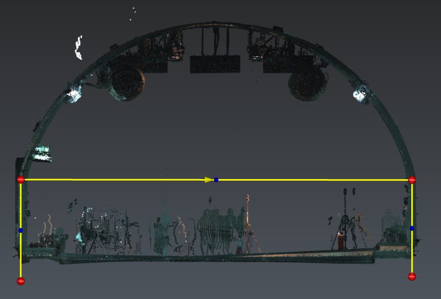
Now, draw manually the bottom side from left to right (Activate only the Nearest snapping mode).
Exit the workflow.
Select Tunnel cloud_unfolded and this polyline, then launch Unfold Cloud.
Set the axis to Y=1 and unfold All points. Validate the command.
This tunnel has a constant slope: thus it is possible to skip this step and give directly the appropriate axis for the last unfold step.
Unfold around X
Show only the Tunnel cloud_unfolded_unfolded, select it and launch Scan to Plan.
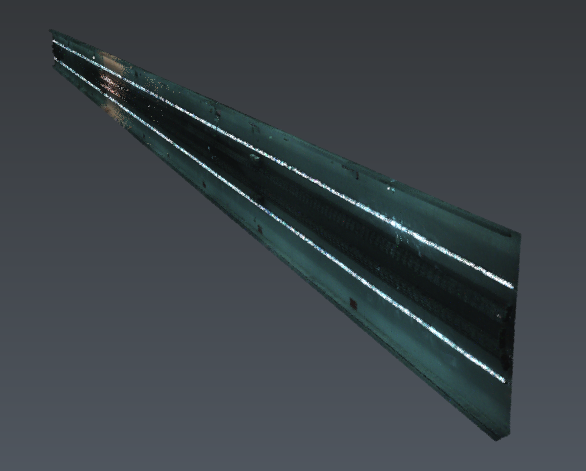
Set the slice to -X mode (only available in Advanced mode) and define Thickness much longer than the tunnel to keep all points (1500m). Then click on the cloud and go to the next step.
Draw the profile manually from the left to the right almost like you did at the beginning but with XYZ snapping mode only. This step cannot be very accurate due to the tunnel imperfections: you have to decide your own rule to define how it will be unfolded.
Select Tunnel cloud_unfolded_unfolded and this polyline, then launch Unfold Cloud.
Set the axis to X=1 and activate Slice selection:
-
Left: 2m
-
Right: 1m
-
Click Preview the selection and Preview. Validate the command.
We can generate an orthoimage, create a grid, insert measure or notes, etc.
It can be difficult to decide the axis for each step even if any unfold result is inserted in XoZ. Remember that you can apply planar symmetry at the end (Symmetry ).