In this exercise, you will create a model of pipe traces.
Open the file PipeTraces.3dr.
Understand what can be edited after extractions
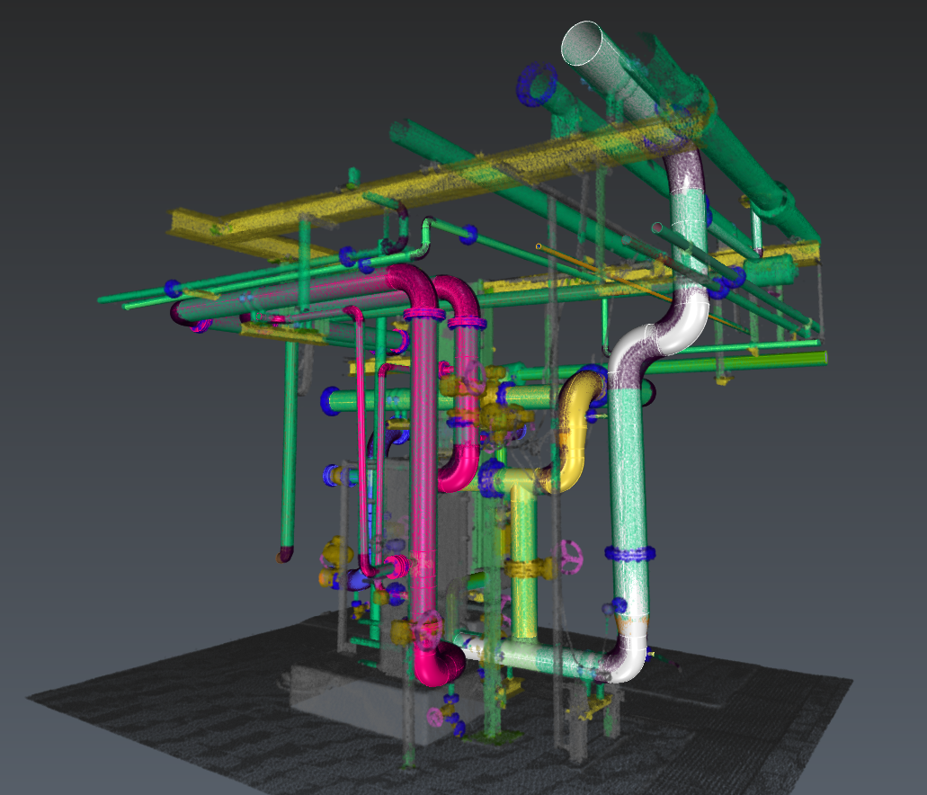
In this file, two Scan to Pipe projects have already been performed to draw pipe traces. Click the play icon next to the folder called Scan to Pipe - ASME/ANSI_mm.
This Scan to Pipe project uses the ASME/ANSI_mm catalog, meaning that the elements are extracted using dimensional characteristics available in the standards contained by this catalog.
Technical information
The ASME/ANSI_mm catalog is installed by default with Cyclone 3DR 2025.2 and above. When sharing a Cyclone 3DR file containing a Scan to Pipe project with a custom catalog, you will need to share it too: see Scan to Pipe - Catalogs for more information.
You enter the first step of the workflow, Extract pipes, where you can see a tree view showing the traces that you can duplicate, zoom on, delete, show/hide or modify their colors.
Note you can also adjust the cloud and pipes transparency, as well as filtering points according to their classification.
Most elements are created using exact or partial catalog references. These are represented with a ![]()
![]()
Technical information
In a catalog workflow, Scan to Pipe provides 3 extraction strategies:
-
Theoretical: all extracted pipe elements will strictly follow catalog references.
-
Adaptive: all extracted pipe elements will be assigned to catalog elements, but some characteristics like the lengths and the angle of the elbow are free, combining the best of both worlds.
-
Real: only the straight pipes will be assigned to catalog elements.
In a catalog workflow:
-
Straight pipes will always be catalog elements.
-
Elbows, Reducers and Branches can be catalog or custom elements.
-
Flanges will always be custom elements.
In the 3D scene, you can click on any pipe element. The corresponding trace in the tree will unfold.
Hover over and click on any straight element in the middle of the white trace and delete it. The trace will be split in two. You can recreate the missing straight pipe by simply connecting the pipes that form its ends:
-
Select an ending element of a white trace and click Connect traces

-
Choose to Connect with straight pipe

-
Select the corresponding other trace extremity.
The two traces are now merged into one. Every individual pipe element has been fitted to its nearby points.
When connecting two traces, the first selected will act as the main trace and won’t be edited nor fitted to the cloud: only the second one will.
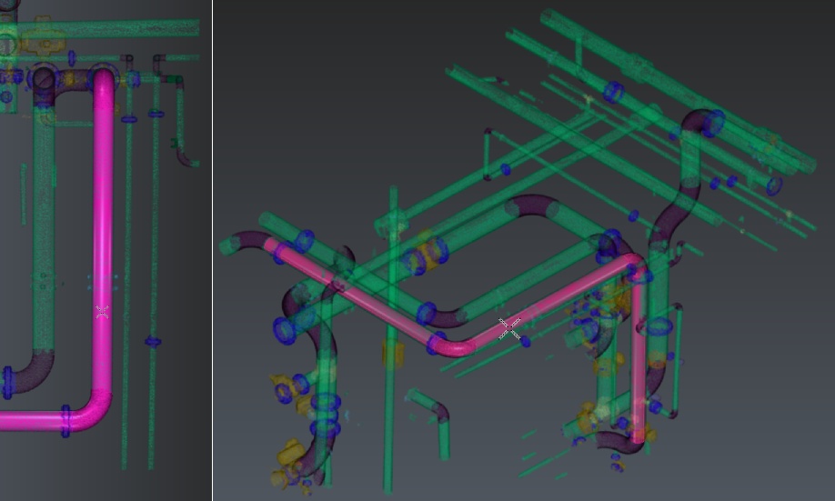
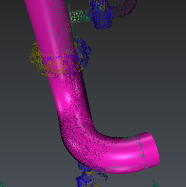
Now select a straight element in the blue trace. Its Pipe reference is 10 from the ASME B36.10M_mm_ standard (0.273m). Set it to 8 (0.2191 m). This new diameter will be propagated until next reducers, on the whole selected branch.
You are prompted with a warning: some pipe elements have lost their standard reference. You may want to reassign them references:
-
Select a (now custom) elbow
-
In its parameters, set it to Catalog

-
Select a new reference: some choices of the list are highlighted with a * before their name. This means they share the same diameter(s) as adjacent element(s) and thus won’t propagate a diameter change at selection
Do the same for the other elbows.
Caution: the geometry of the elbows in the trace may restrict the diameter (for instance, try to set an elbow reference to 14).
In the same way, if you move the editing arrows of a custom element, the adjacent ones will be modified. Globally, extend or shorten the straight elements is not necessary unless the element is located at the end of the trace.
If an element is fully constrained by its adjacent elements (e.g. a straight pipe between flanges or catalog elements), no editing arrow will be displayed in the scene.
Still on the blue trace, select an elbow. You can change the diameter like you did with the straight element. You can also modify the bend radius (either through the pipe reference or the Bend Radius dropdown). The angle can only be modified when the elbow is the last element of the trace.
Click the elbow at the top end of the trace: as it is referenced, its angle is limited by what is available in the standard. In this case, 45° and 90° can be chosen. You may set it to ![]()
This is very useful for traces ending with an elbow or when they deviate from the cloud (due to a lack of points for the extraction algorithm). In such case, delete the inaccurate elements, adjust the elbow angle and continue the trace from this elbow using a straight pipe.
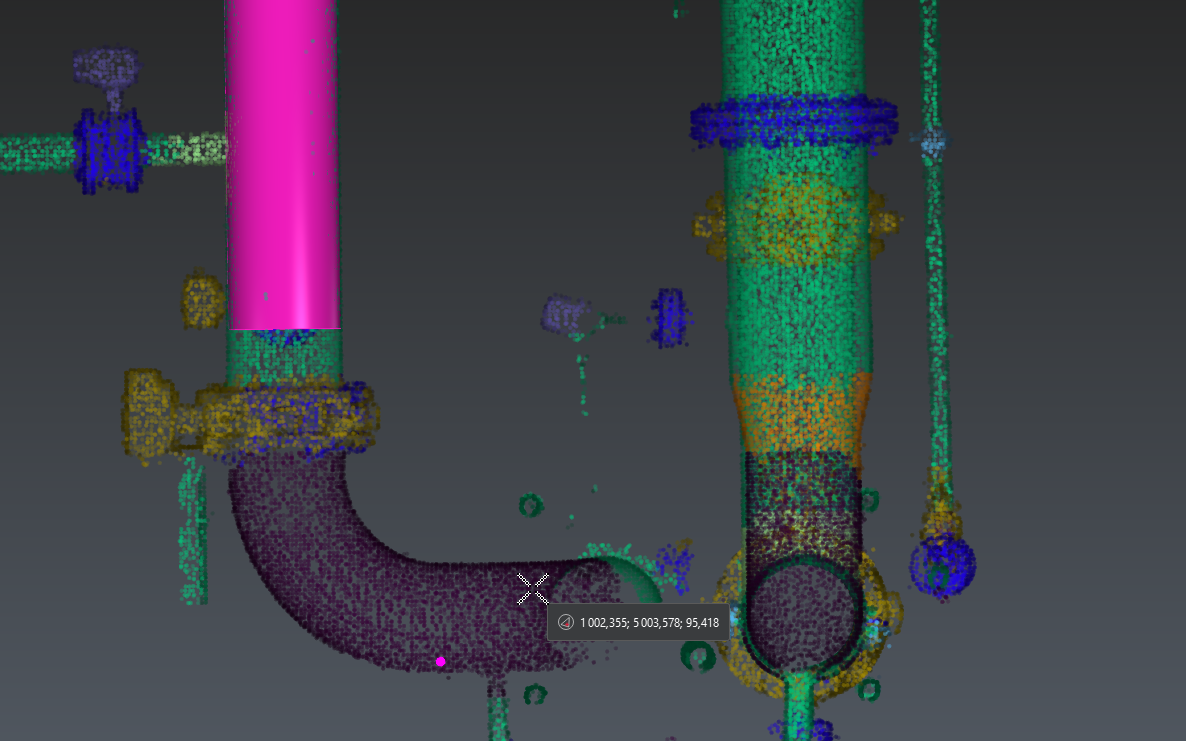
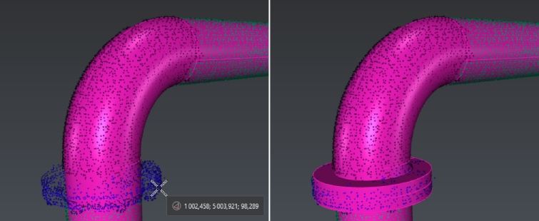
Select a reducer at the bottom of the trace. As it is also catalog, you may edit its characteristics like you did for straight and elbow elements. Note that a reducer can be concentric or eccentric. This setting is only editable if at the trace extremities. Delete an adjacent straight pipe to be able to edit it.
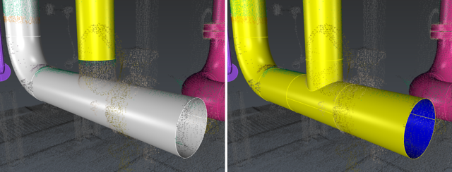
Finally, select the vertical straight element at the bottom of the yellow trace and Connect it to the white trace using a Y/T branch in 
![]()

Note that the new merged trace will inherit the yellow color of the first selected trace.
At every extraction or connection, the whole trace will be fitted to the cloud to ensure every single element fits best to the scan. It may generate some seemingly unviable elements: an orange warning will appear next to the trace name in the dialog box. In that case, unfold the trace to see which element is causing an issue. Select it and click on the magnifying glass to focus on it and be able to fix the issue. This warning is only a visual indicator, it won't restraint any editing capability.
To conclude: keep in mind that the properties of the first selected element will be propagated. You should always start the propagation with the most reliable elements, especially considering their direction and diameter.
Extraction
Exit the current workflow and hide it. Select the cloud and launch Scan To Pipe. Set extraction mode to catalog: select ISO catalog. Using the classification filter, uncheck unclassified and steel structure points to hide the ground and steel elements, thus helping the extraction algorithm.
Tips
You may also hide classes representing objects that can not be extracted by Scan to Pipe tool, such as Tanks or Valve handles.
Select Start new trace. Use the Auto extraction tool and check Symmetric reducer: for best best results, click on a well-defined, low noise and long enough straight pipe. It is not necessary to begin with an extremity because any extremity of the trace can be extended at any time.
In Adaptive and Real extraction modes, check Use standard angles to constrain the elbows to common values: here we got two exact 90° angle elbows. Extraction may differ slightly according to the clicked point.
The auto extraction tool did not extract the whole trace. With the tool still active, click on a further part of the cloud. The trace will be extended.
At any point, if the extraction is not satisfying, press Delete on the keyboard to cancel the latest extraction and continue from where you were previously.
If you want to extract elements that are less well-defined and / or incomplete, you can switch to semi-automatic extraction. Select Elbow + Straight pipe mode and click two points on the opposite extremities of the next straight to extract to get a finer result:
Note that the end to be extended or reduced will be found automatically. The workflow works the same for extracting reducers as well as for straight pipes.
Flanges work differently: they rely on an existing straight element. Select a trace and click Continue trace. Click Flange in the toolbar and extract a flange on the upper part of the extracted trace.
As well, if the extraction did not go well, press DELETE to make a new extraction.
Click Validate trace and exit to quit the extraction tool. Repeat this workflow to extract all the desired pipe traces:
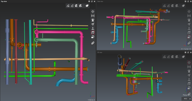
When all traces are drawn, go to the next workflow step: Export pipes.
Export
For BIM export, you can rename pipe elements and give them a thickness using the list (double click on the default thickness). Otherwise, select directly the appropriate export among:
-
COE: pipe traces, optionally export the nominal diameter instead of the external diameter
-
BIM: pipe traces, optionally as parametric solids.
-
Mesh: pipe traces, optionally with textures, will be exported with discretized surfaces. Optionally, send directly the traces to another application: refer to Send to.
-
CAD: pipe traces will be exported using geometrical CAD shapes.
-
Linear: only the center axis and the profiles will be exported.
-
Table of pipes information: a csv table describing the traces will be exported.