This guide details the workflow for adjusting a point cloud imported into CloudWorx for Revit at an incorrect angle.
This misalignment can occur, for instance, when a point cloud lacks a defined coordinate system set beforehand in legacy software or when a drafter is unaware of the data source. Therefore, it is essential to orient the coordinate system of the imported point cloud in the correct direction and ensure it aligns parallel with one of the main axes, which is typically preferred for modelling purposes.
Practice data
Importing Project Data
-
Import a dataset using an appropriate import option. Refer to the Connect To Help section for more details.
In this workflow, a dataset is saved as the LGSx file, which is then imported as follows:
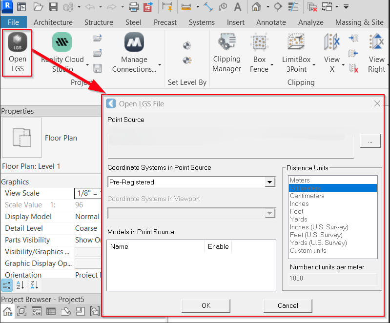
1.1. In the Project panel, click Open LGS File and browse to the required file.
1.2. In the Coordinate Systems in Point Source field, select Pre-Registered.
Tip: Always review the available coordinate systems in the project, as one of them may have the correct orientation.
1.3. Click OK.
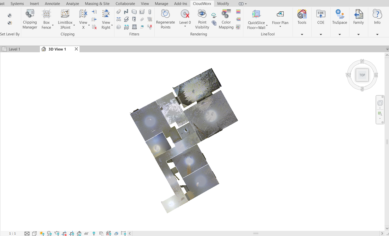
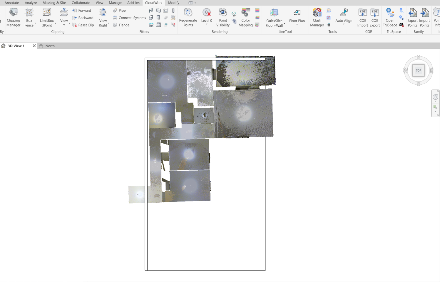
As a result, the dataset has been imported; however, it is not aligned properly.
Adjusting Levels and Coordinate System Points
When starting a new project in Revit, it’s essential to set a coordinate system in the correct direction. To ensure accurate model positioning, you need to adjust levels so that they align with the elevations of the imported point cloud and place the project base point and the survey point.
Creating Slice
-
Create a slice to temporarily hide unnecessary points:
2.1. In the Clipping panel, click the Slice drop-down list and select the axis to which the view should be aligned.
2.2. Define two points for the slice planes’ location.
Moving Levels in Elevations
Adjusting levels in Revit is essential for the accurate visualisation of the CAD geometry at the correct elevations in the 3D view. While levels can be established using the CloudWorx Set Level command, the method described below can help to average out the floor across a large area, particularly when dealing with uneven floors.
-
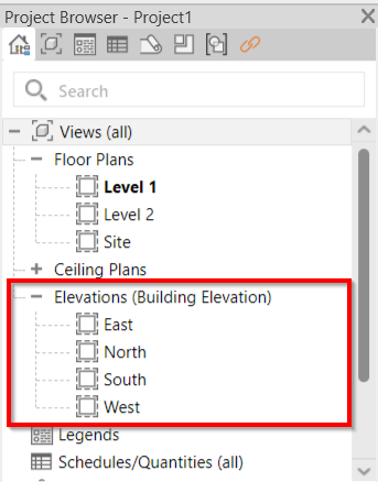
In Revit’s Project Browser, navigate to Elevations and select the desired elevation view. In this case, it’s North.
3.1. Drag Level 1 to match the floor.
3.2. Drag Level 2 to match the ceiling.
-
Go to CloudWorx | Rendering and click Regenerate Points to ensure all changes are reflected correctly.
Placing Project Base and Survey Points
-
In the View Control Bar at the bottom of the Revit window, click the Reveal Hidden Elements icon

-
Move the project base point to define the 0, 0, 0 origin of the project.
-
Move the survey point to define the real-world coordinates of the project as follows:
7.1. Uncheck the paperclip before moving the survey point.
7.2. Adjust the position of the survey point. Since the project in this workflow lacks real-world coordinates, the survey point is moved to the same location as the project base point.
7.3. Recheck the paperclip after the move.
-
Сlick

Disabling Active Clipping
-
Go back to the 3D view.
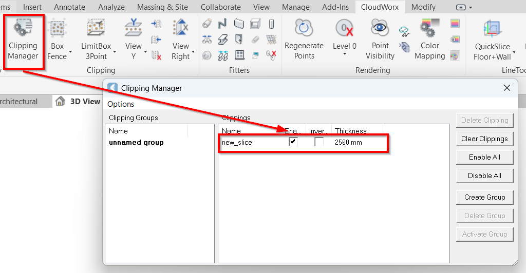
-
Open the Clipping Manager and disable the clipping used to adjust the coordinate system parameters. The whole point cloud will now be visible again.
Aligning Point Cloud
Creating CAD Geometry
Before aligning a point cloud, you need to create a CAD object to which the point cloud should be adjusted. Since we are using an apartment model in this workflow, we will create CAD geometry as follows:
-
Navigate to Revit’s Architecture tab, select the Wall tool and draw a wall.
Tip: Press and hold the Shift key while creating a wall to make it perfectly aligned with the selected axis.
-
Go to the Structure tab and create a foundation plane. In this case, select Slab and draw a rectangle defining a floor boundary.
Matching Point Cloud with CAD Object
One of the most efficient methods for aligning a point cloud with a CAD object is through auto-alignment. While manual alignment is also an option, it requires an understanding of the distances between the point cloud and the objects that need adjustment, which can be a complex task. In this workflow, the auto-alignment by three planes will be demonstrated.
-
Switch back to CloudWorx.
-
Navigate to the Tools panel and select Auto Align.
-
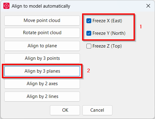
In the Align to model automatically dialog, take the following steps:
15.1. Select the Freeze X (East) and Freeze Y (North) check boxes to ensure the point cloud only rotates around the Z-axis and does not tilt.
15.2. Select the Align by 3 planes option.
-
Select three cloud points to grow three planes by which the point cloud should be aligned with the model.
-
Select three points on the CAD model planes to match them with the selected point cloud planes.
Once done, the point cloud will be automatically aligned with the model.
Fine-Tuning Point Cloud Alignment
After the automatic alignment, you may notice that some structures are not built at perfectly right angles. To achieve a more accurate alignment, you may need to make additional adjustments or carefully reselect planar surfaces.
In this case, the rotation tool will be beneficial for fine-tuning.
-
Switch to the TOP view to check for any alignment inaccuracies.
-
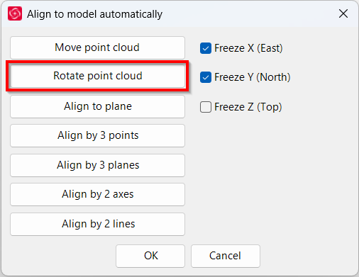
Go to Tools | Auto Align.
-
In the Align to model automatically dialog, select Rotate point cloud.
-
Pick a corner point - rotation center, pick the rotation start point, and then pick the rotation end point. The adjustment will occur automatically.
Tip: Always check the bar at the lower-left corner of the Revit window for real-time instructions while using the tool.
-
To better visualise the result:
22.1. In the Rendering panel, click Point Visibility to turn off the visibility of points.
22.2. Select the created CAD objects and delete them.
22.3. Click Point Visibility again to turn on the visibility of points.
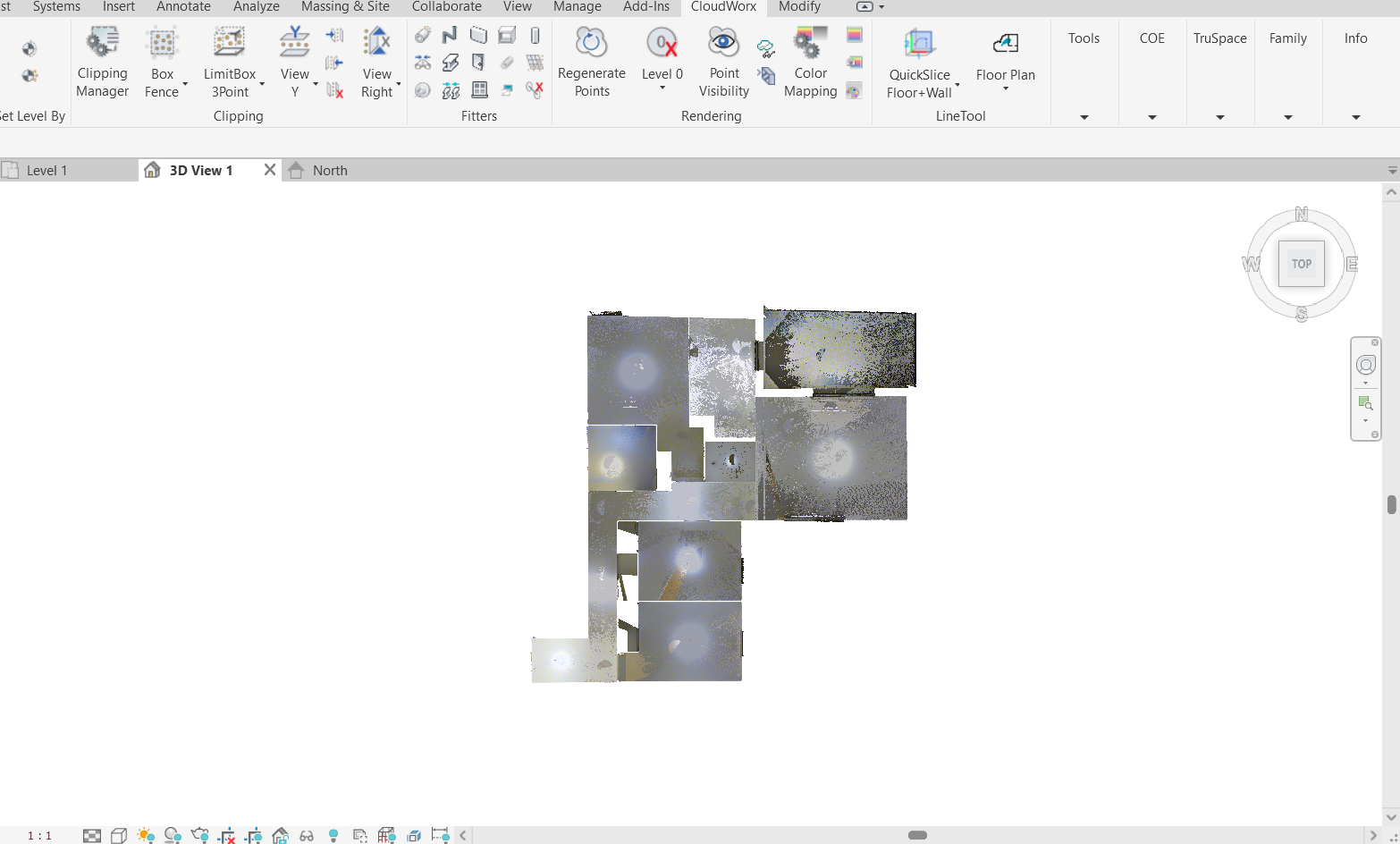
The point cloud is now correctly aligned with the axes.