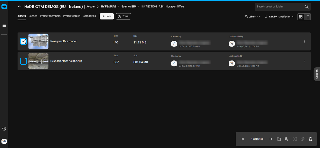
Navigate to the Assets you wish to combine in a scene and select them by activating the check box. The assets must be in the same project.
We recommend creating a folder for the Assets within the project to make location of the matching assets as simple as possible.
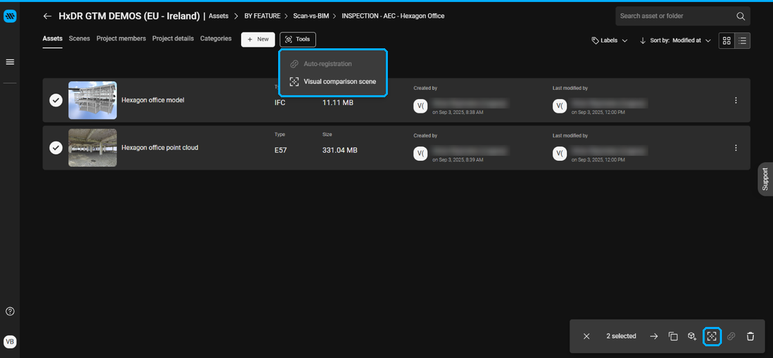
Click Tools then Visual comparison scene.
Alternatively, you may click the quick access Visual comparison button that appears at the bottom right of the screen.
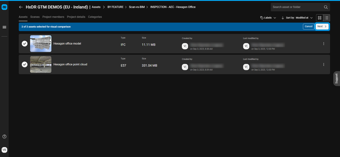
Ensure that the appropriate number of Assets are selected and click Next.
At this time, only two Assets at a time can be compared.
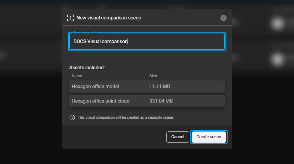
Name the Scene and click Create scene.
You will be placed into a side-by-side view of the two assets.
At the top of the screen, your progress within the workflow will be displayed.
Below the progress bar, the instructions for the current step will be displayed.
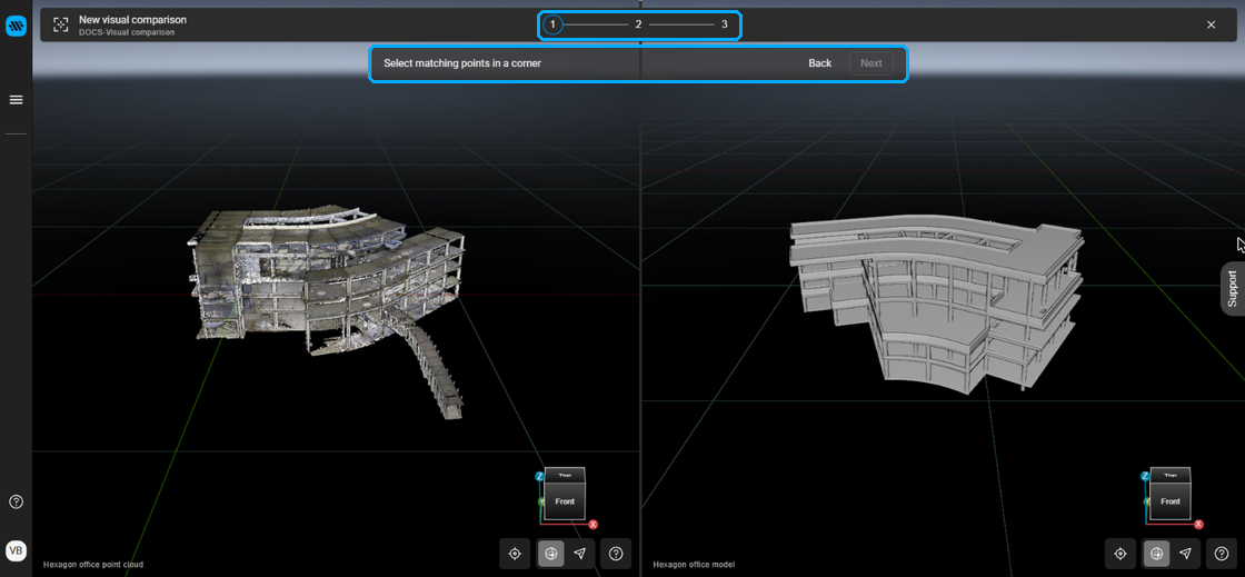
Identify distinct, matching points in both the model and the point cloud. You may pan, rotate and zoom in each asset independently to orientate to the desired points.
A magnification window will display a close-up view of the cursor to aid in precise picking.
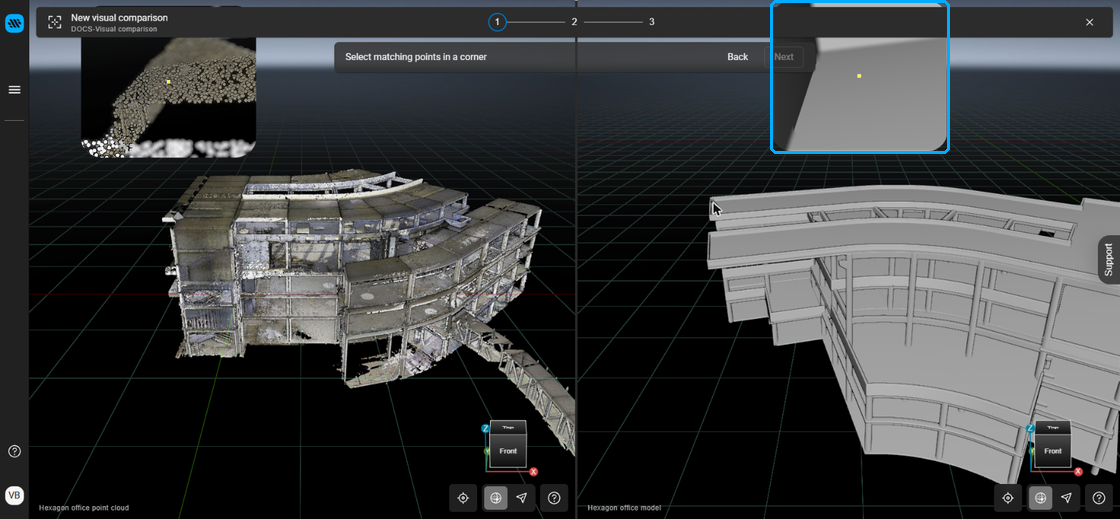
Begin by selecting a common point on each Asset. Precise point picking is important to ensure an accurate alignment.
After a point is selected, a marker will be placed. The point on either Asset can be adjusted.
Select Next.
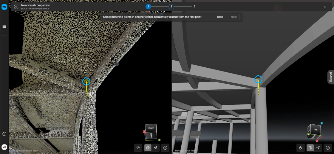
Identify a horizontally distant point and repeat the point selection process in each node.
Select Next.
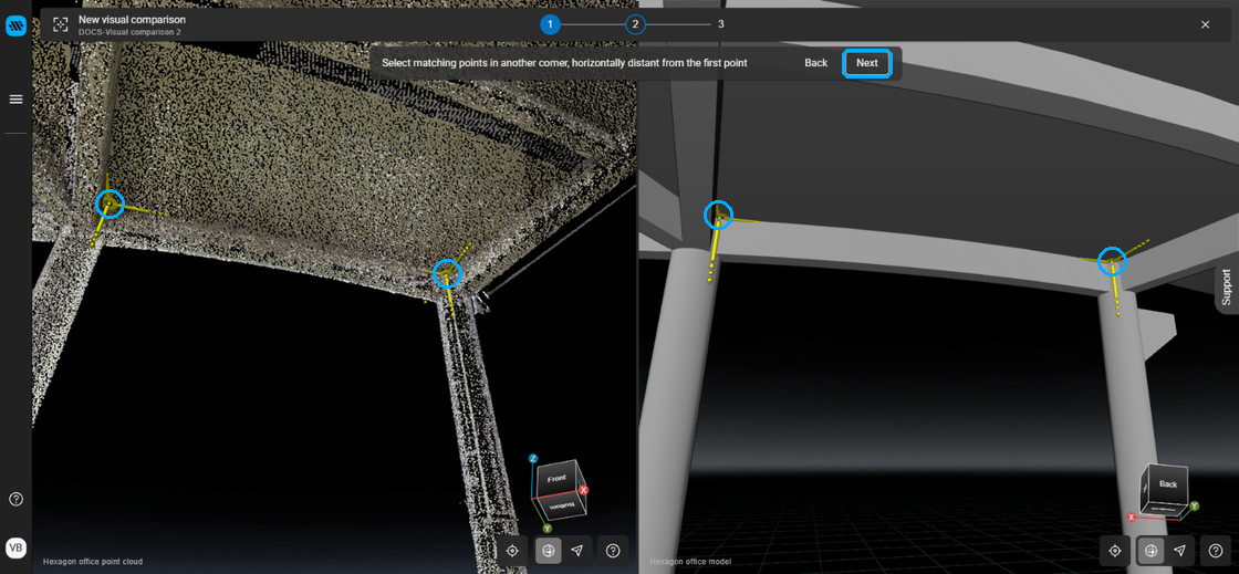
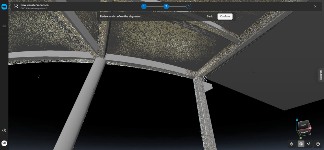
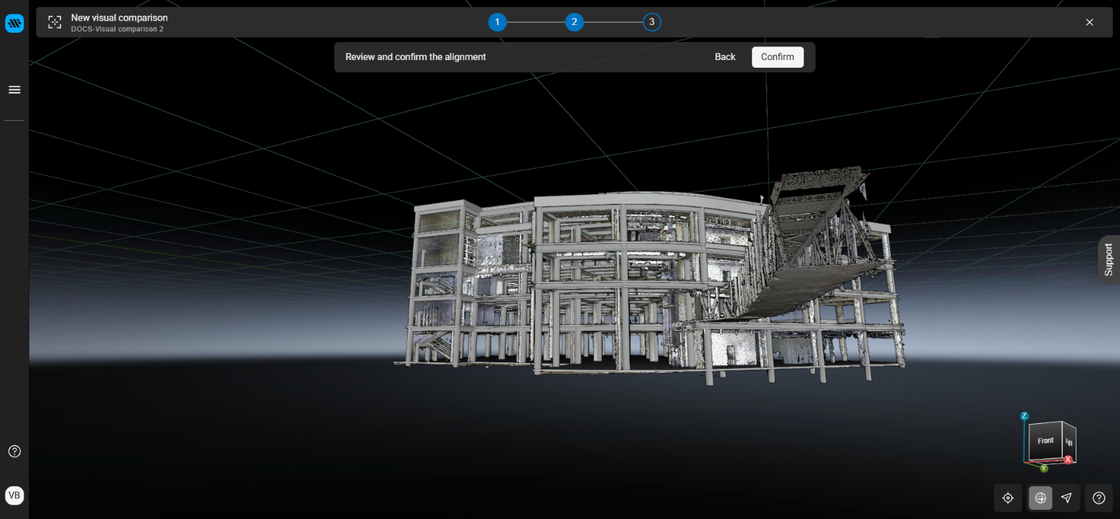
Review the alignment by visually inspecting the two nodes at various places within the alignment. You will want to see areas of intermingled points and model.
You may use the adjustment arrows to further refine the alignment or re-run the alignment from the beginning if you are not satisfied with the results.
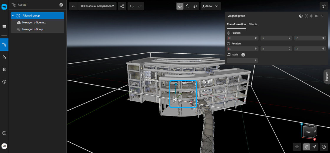
Directional movement arrows
After you are done with your manual alignment steps, you can press the Auto-align button to fully align your reality capture scan with your BIM model to the highest accuracy.
Launching Auto-Align after a manual alignment has been completed
Select Confirm to complete the alignment.
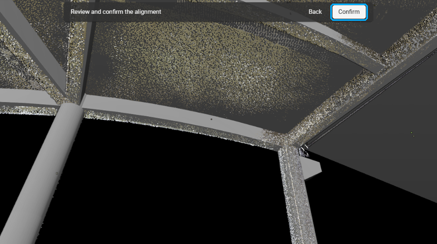
Once aligned, you may also adjust the visualization of the model or point cloud to better see the alignment.
We recommend switching from the standard grey model color to a more high-contrast color to inspect the alignment thoroughly.
Select the Asset.
Select Effects.
Unselect the Inherit from parent node box.
Select Color.
Select the desired color.