The Georeferencing workflow enables the targets extraction and fitting directly from the raw data of a connected RTC360 scanner, or using natural targets from within the point clouds in the App. You can assign real-world coordinates and compute the transformation directly from the raw data of RTC360 scanners and assign real-world coordinates to a point cloud
Workflow
Step 1- Enable the workflow and load your Control Points file in the Job Creation panel
Start your usual scanning workflow connecting the scanner to the Field360 App and creating a new Job. In the Job creation panel, tick the Georeferencing checkbox to enable the workflow and attach the Control Point file (both .csv and .txt format are supported).
You can load the Control Point file at later step as well, from the Control Point Manager.
In both cases, to load the file in the Control Point Manager:
-
Click on the red Control Points button
-
Import from file
-
if the file has been loaded in the Job creation step, it will be available in the drop down list
-
if not, you will be redirected to the device storage browser
-
-
Review
-
Remove header
-
Choose the delimiter
-
-
Import
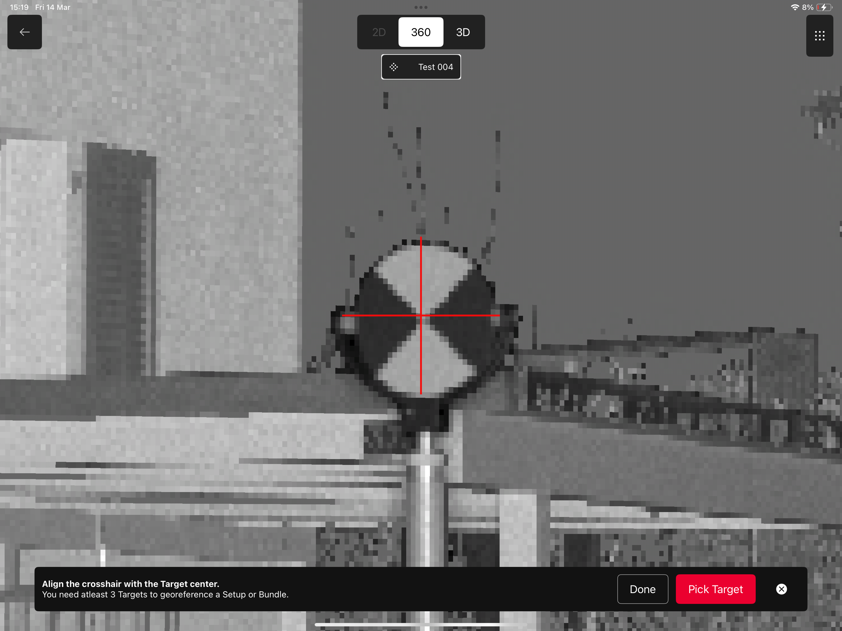
Step 2- Collect data and Extract targets center
Connect the Field360 App to an RTC360 scanner and gather a scan. Select the setup and start the Picking Target mode: navigate in the Panoramic Images and center the crosshair to the center of the Control Point, then click Pick target.
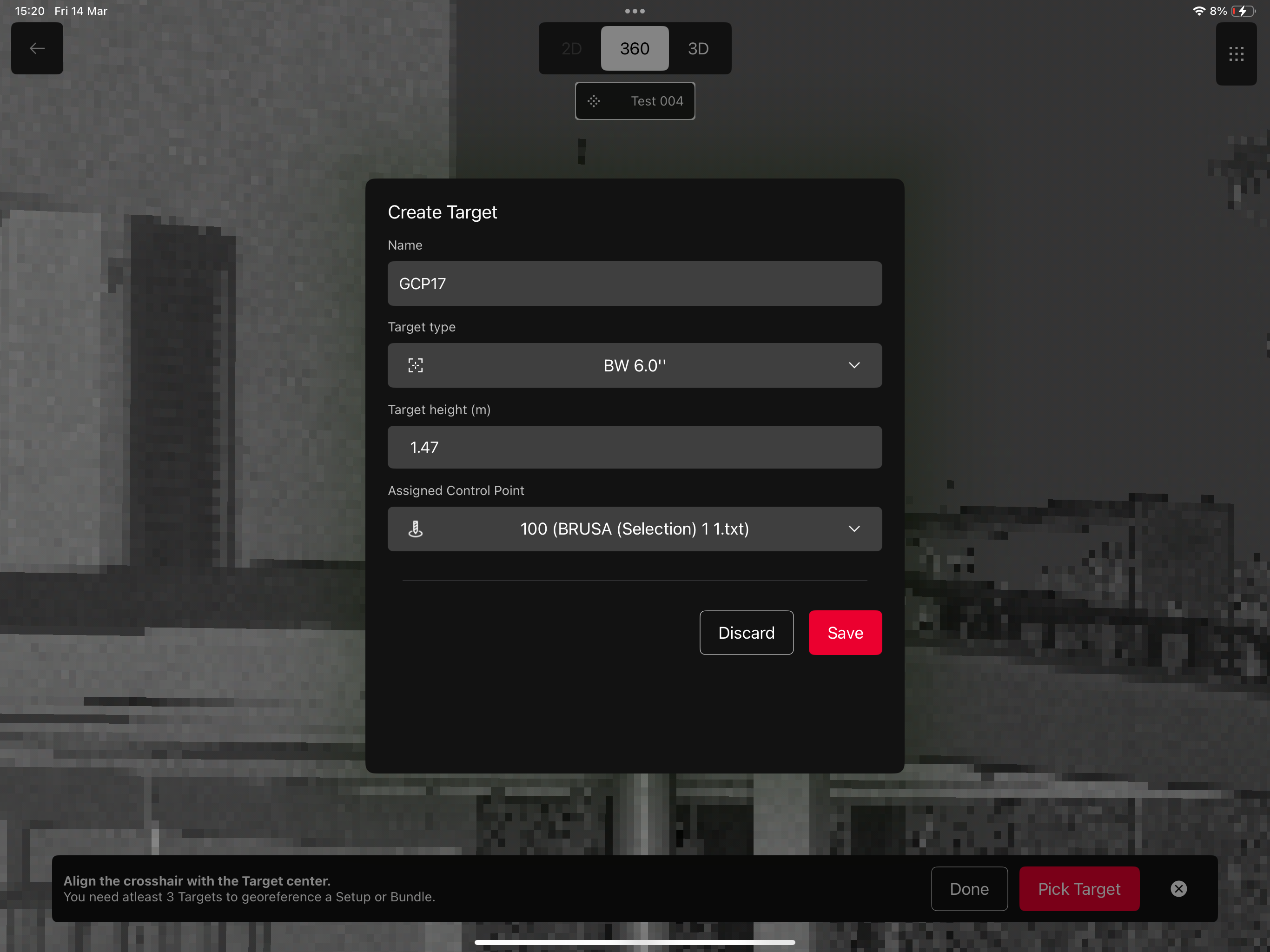
You will see the Target Creation panel, where you can enter:
-
Target Name
-
Target Type (Black and White 4.5'' or 6'' and Natural)
-
Target Height
-
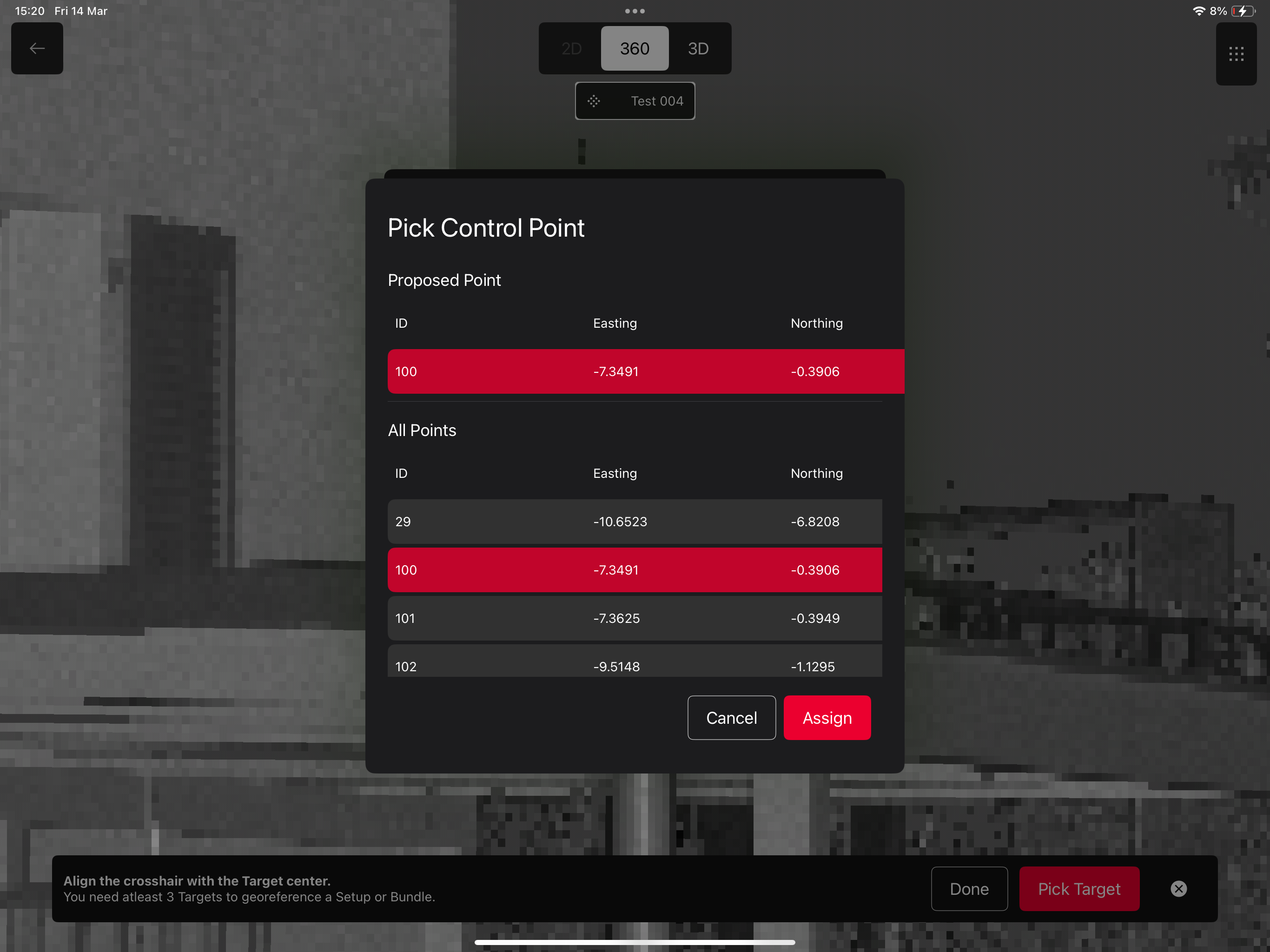
Assigned Control Point field: here you can select the Control Point to assign to the target from the full list. The system anyway is going to propose a Point.
-
Run the Target Fitting
Step 3 - Assign/modify Control Points and Calculate
Once the Target Picking and Fitting is done, and the control Points have been assigned, you can review the residuals and Include/exclude targets from the calculation directly from the Assignments/Results Table.
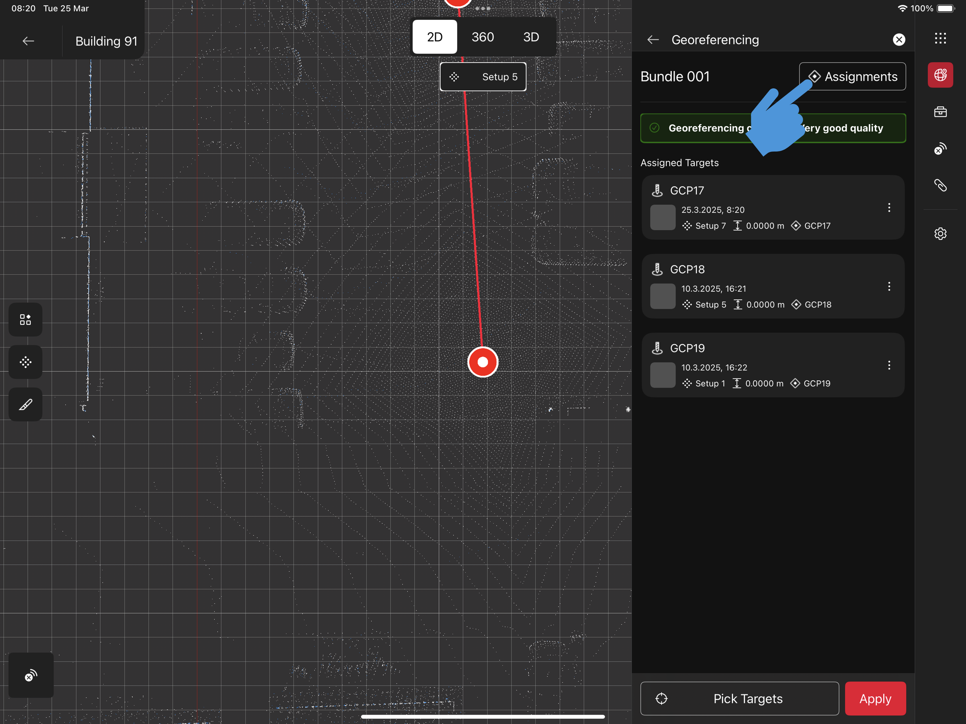
To do so, please use the 3 dots menu to unassign the Control Point, and the chevron icon next to the Contro Point column to change the assignment. In this Table you can also clear the Geo-referencing.
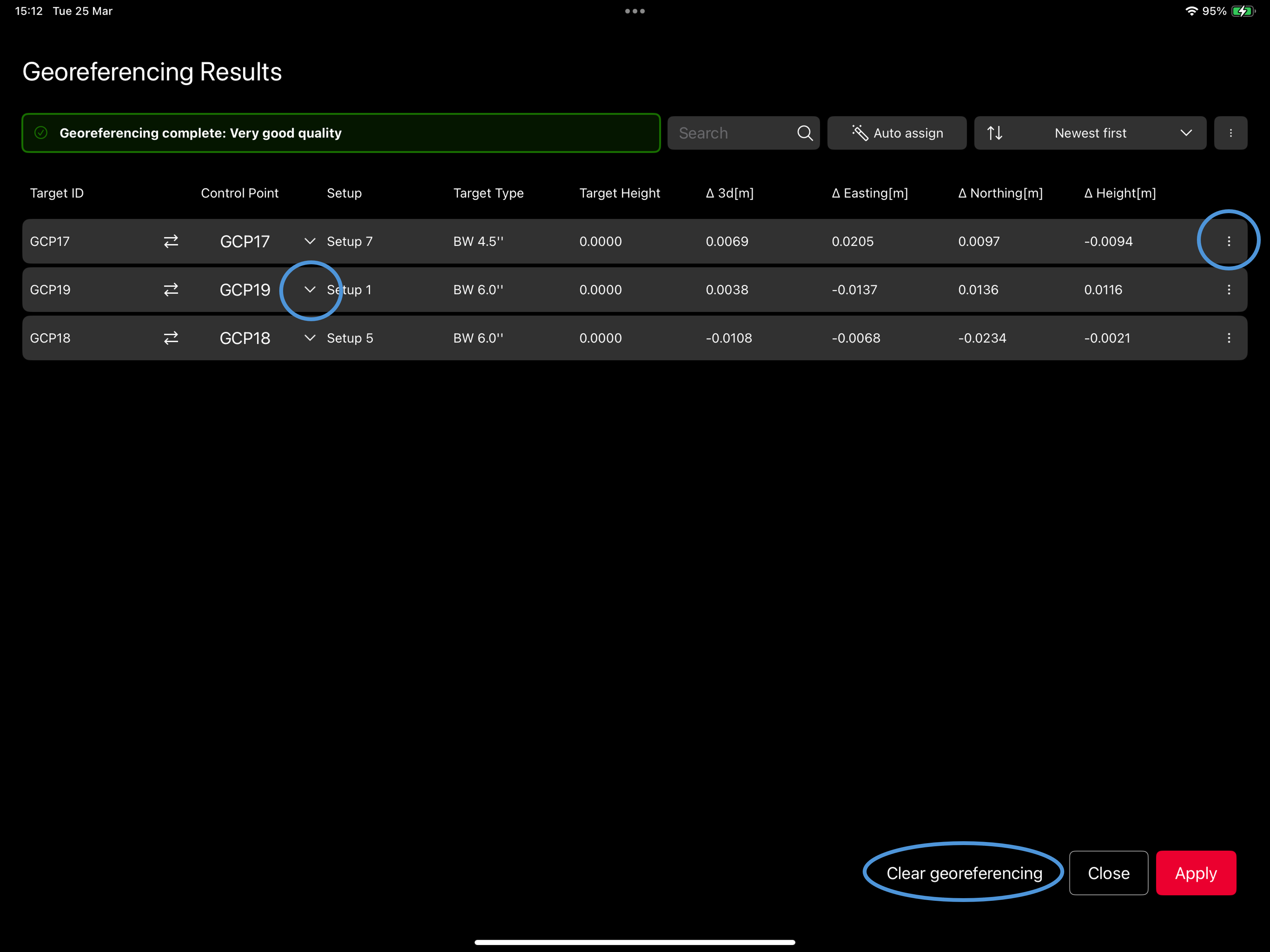
The Control Point assignment can be also run automatically from the main Georeferencing panel or from the Assignments/Results Table through the Auto Assign button
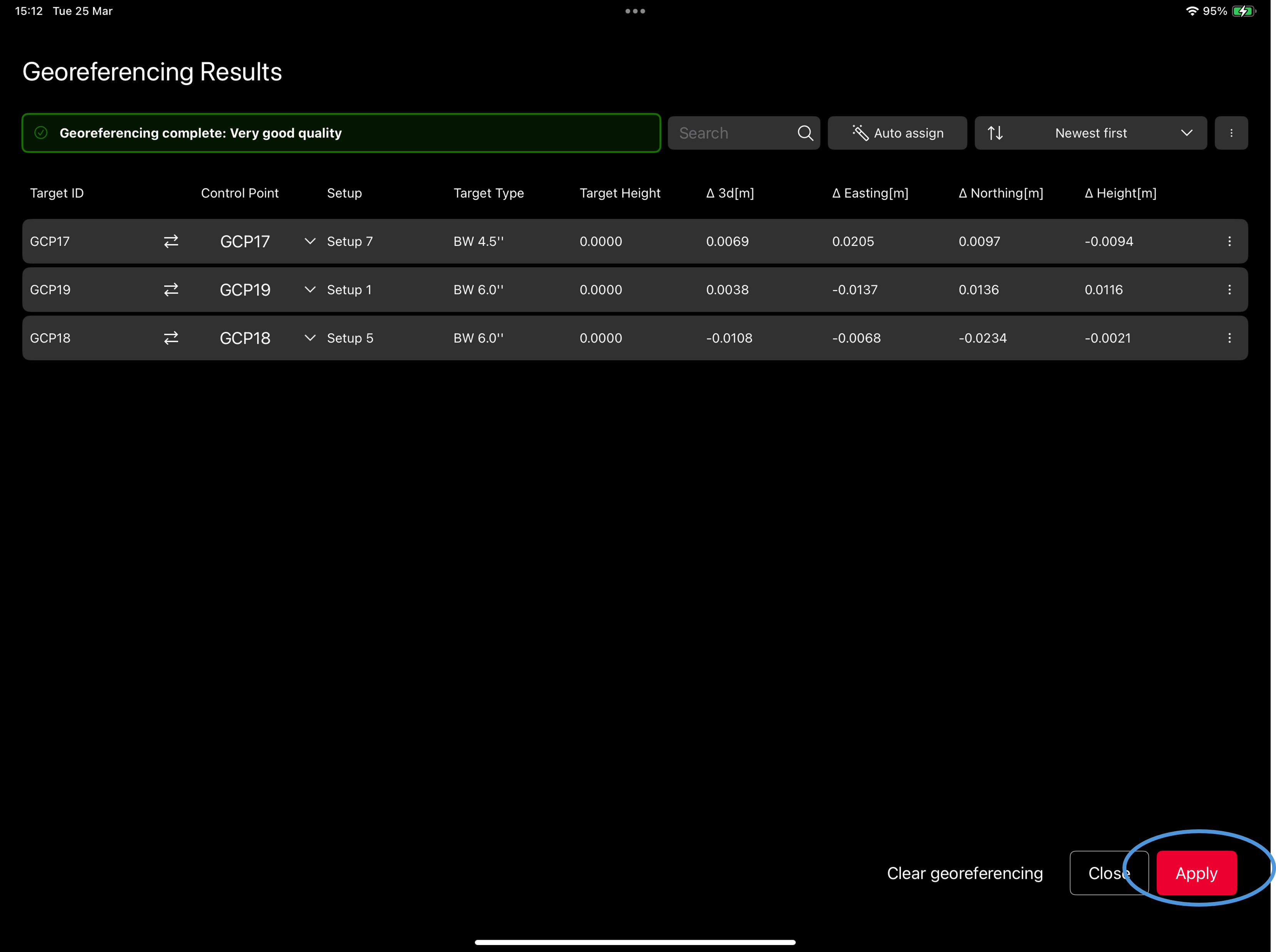
Step 4 - Apply Transformations
Once you picked and fit all the Targets, and assigned the Control Points, Apply the mathematical transformations to adjust the Point Cloud data from its original coordinate system to the desired geographic coordinate system.
As before, you can do it from both the main panel and the Assignments/Results table with the Apply button.
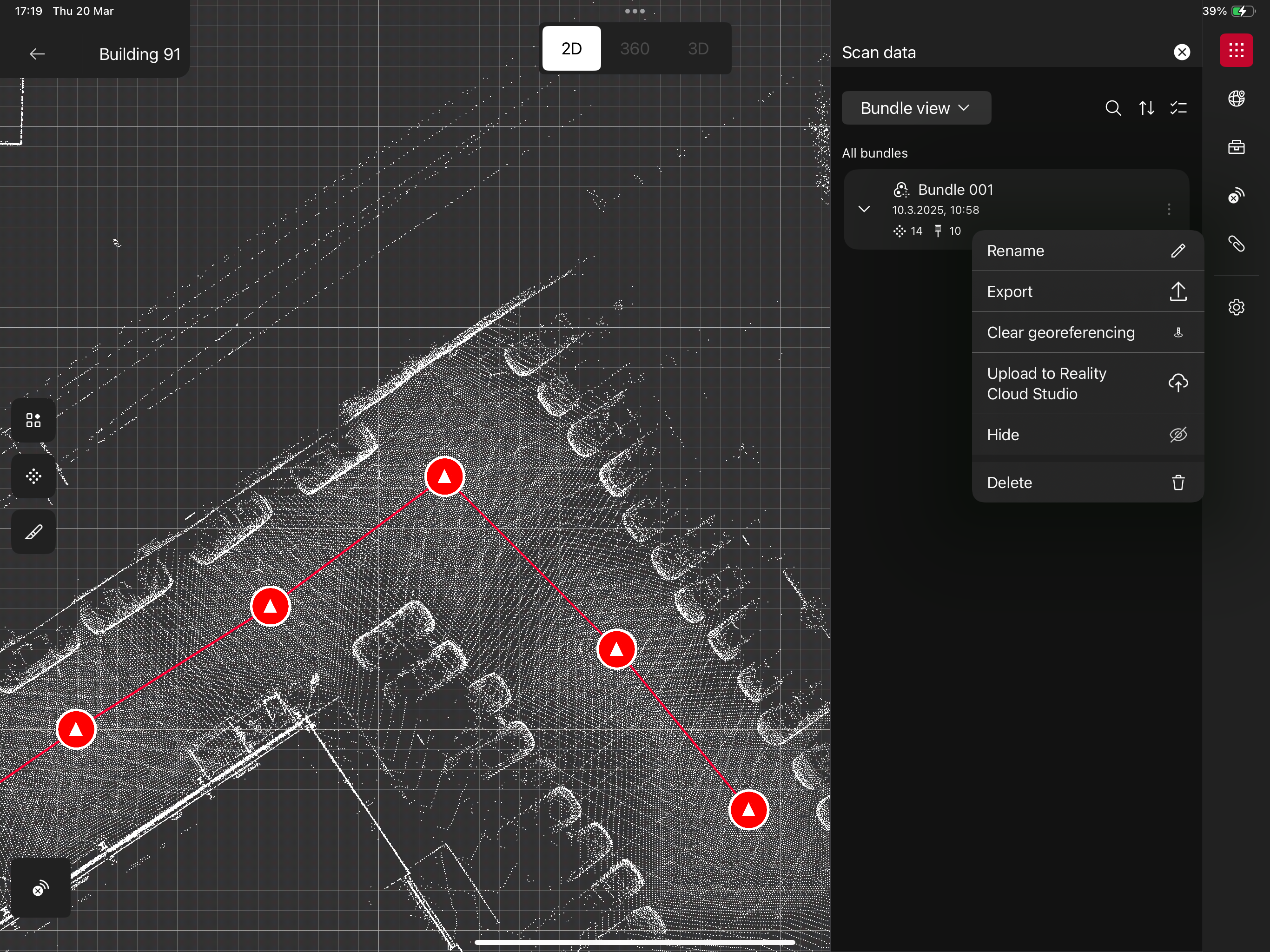
Step 6- Georeferencing Results
The icons of the Setups will now turn into triangles: this indicates that your data are Georeferenced and the position is locked.
To clear the Georeferentiation and reset the assignments as well as the transformations, please use the command “Clear Georeferencing” in the Residuals/Results table or in the Data Browser item Menu
-
The positions are locked and cannot be moved/rotated
-
The links between locked setups cannot be re-calculated and bundle optimization will not be applied
-
Newly added setups can become locked by applying the transformation again to the bundle
General Requirements and Best Practices
-
RTC360 FW 7.0 required
-
Scanner must be connected to FIELD 360 application
-
Supported target measurement range:
|
12 mm resolution |
6 mm resolution |
3 mm resolution |
|---|---|---|
|
Max 5 - 10 m |
Max 10 - 15 m |
Max 20 - 25 m |