The polygonal mesh modeling created by the software generates models, made up with hundreds or thousands of non-continuous triangles. These 3D meshed models are ready for rapid prototyping, tool path generation, simulation, analysis, etc.
However, a “continuous” model is sometimes required by CAD-CAM software. This process of making a CAD model is also called “reverse-engineering” because you generate a continuous model, also called “exact model” from scattered data sets: mesh and point cloud.
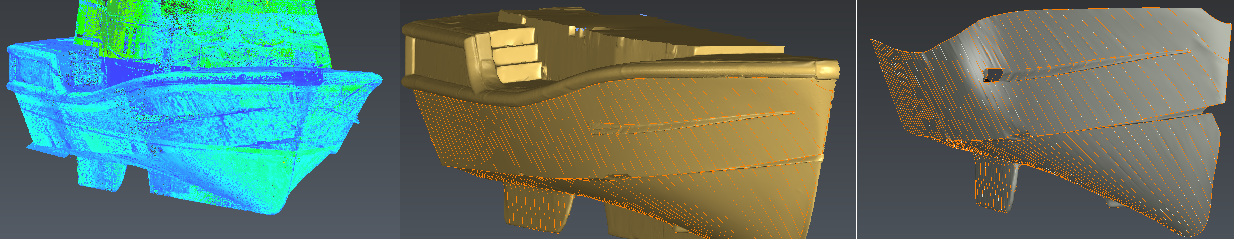
This module allows you to make CAD Surface reconstruction starting from a mesh. The CAD Surfaces generated are NURBS and BSpline surfaces that are fitted on your original mesh. Finally, these surfaces can be exported into IGES or STEP files and/or used to process inspections.
The process to create surfaces from a 3D mesh is divided in 3 parts:
-
First, you have to create a polyline network in order to delimit the different zones having similar curvature properties on your mesh: fillet, planar zone. These lines must lie “on” the mesh.
-
Then, this network of lines is used to create NURBS / BSpline curves using an automatic tolerance which can be modified.
-
Finally, we create NURBS / BSpline surfaces using previous BSpline curves. These surfaces are fitted on the mesh.