
What’s New
Cyclone 3DR 2025.2.0 is a major release that includes new features and improvements to the product.
The main changes and new functionalities are summarized here:
-
Modernized measurement experience [Standard Edition]
-
Catalog fitting within Scan to Pipe [Plant Edition]
-
Tolerance Checking [AEC Edition]
-
Unfold point cloud along polyline [Survey Edition]
-
New “Edge & Corner” detection tools [Standard Edition]
-
Point Cloud Classification updates [Survey, AEC and Plant Edition]
-
Updated engine with the latest NVidia components
-
New performance optimization option
-
New Plant and Heavy Construction Site models
-
-
Support of Multi Sensor LGSx projects [Standard Edition]
-
New tools into Cyclone 3DR Free Viewer [Viewer Edition]
-
Free Move
-
Additional measurement tools
-
Measurement | New functionalities
Within Cyclone 3DR 2025.2, the measurement experience is deeply modernized with the purpose to improve the user experience and to give more capacities to users. The enhancements are detailed in this section.
This feature is available to users with all Editions of Cyclone 3DR, including the Viewer.
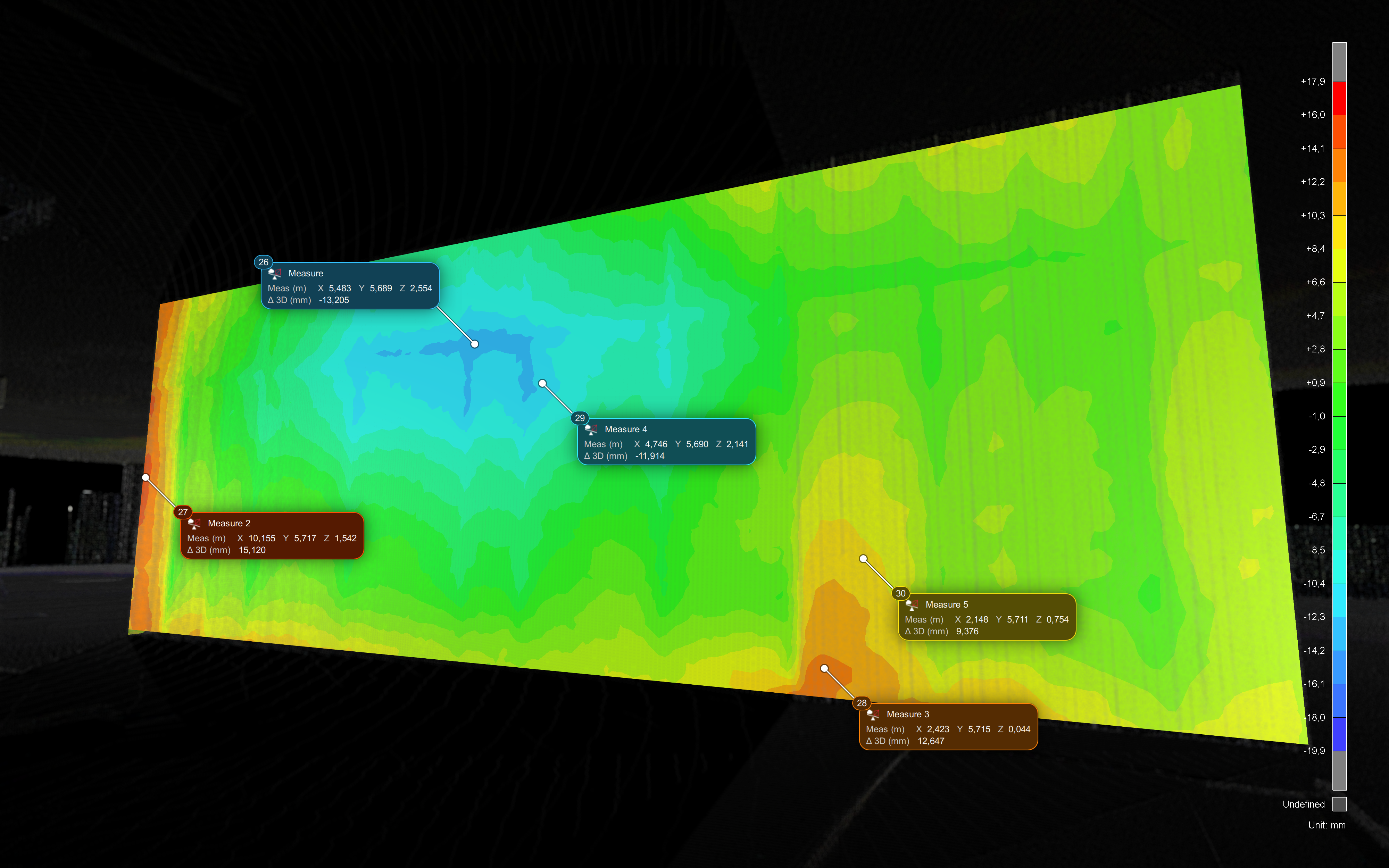
Style
Background
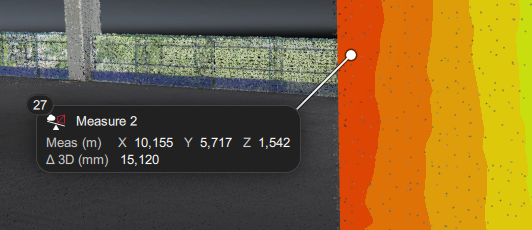
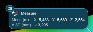
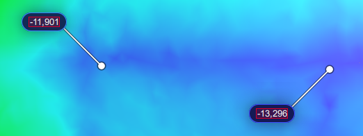
Measures have a new dark background.
In the report editor, it is possible to switch between dark and light background.
|
Dark style |
Light style |
|---|---|
|
|
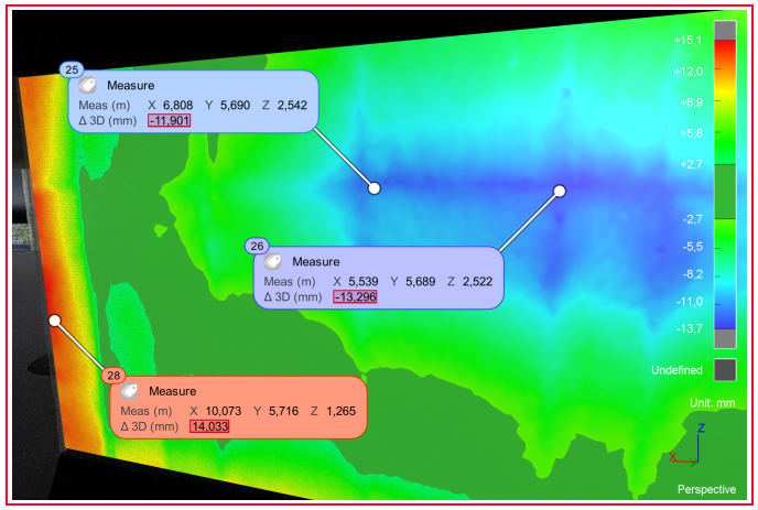
The background color can be made dynamic according to the associated color map.
|
Toggled ON |
Toggle OFF |
|---|---|
|
|
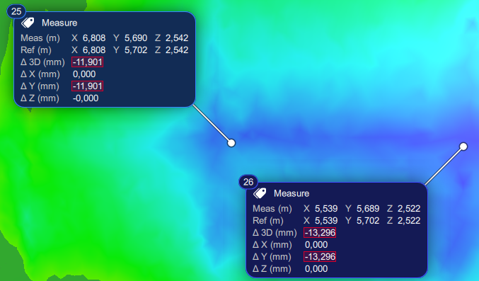
Improvements of the contents
The contents are displayed with more clarity:
-
Contents are presented with rows and not through a table anymore.
-
Units are displayed.
-
Coordinates are presented in a single row.
-
Comments can be added with no limitation of string characters.
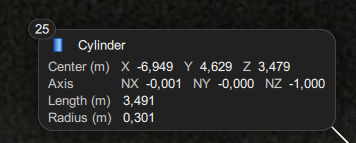
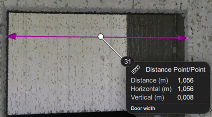
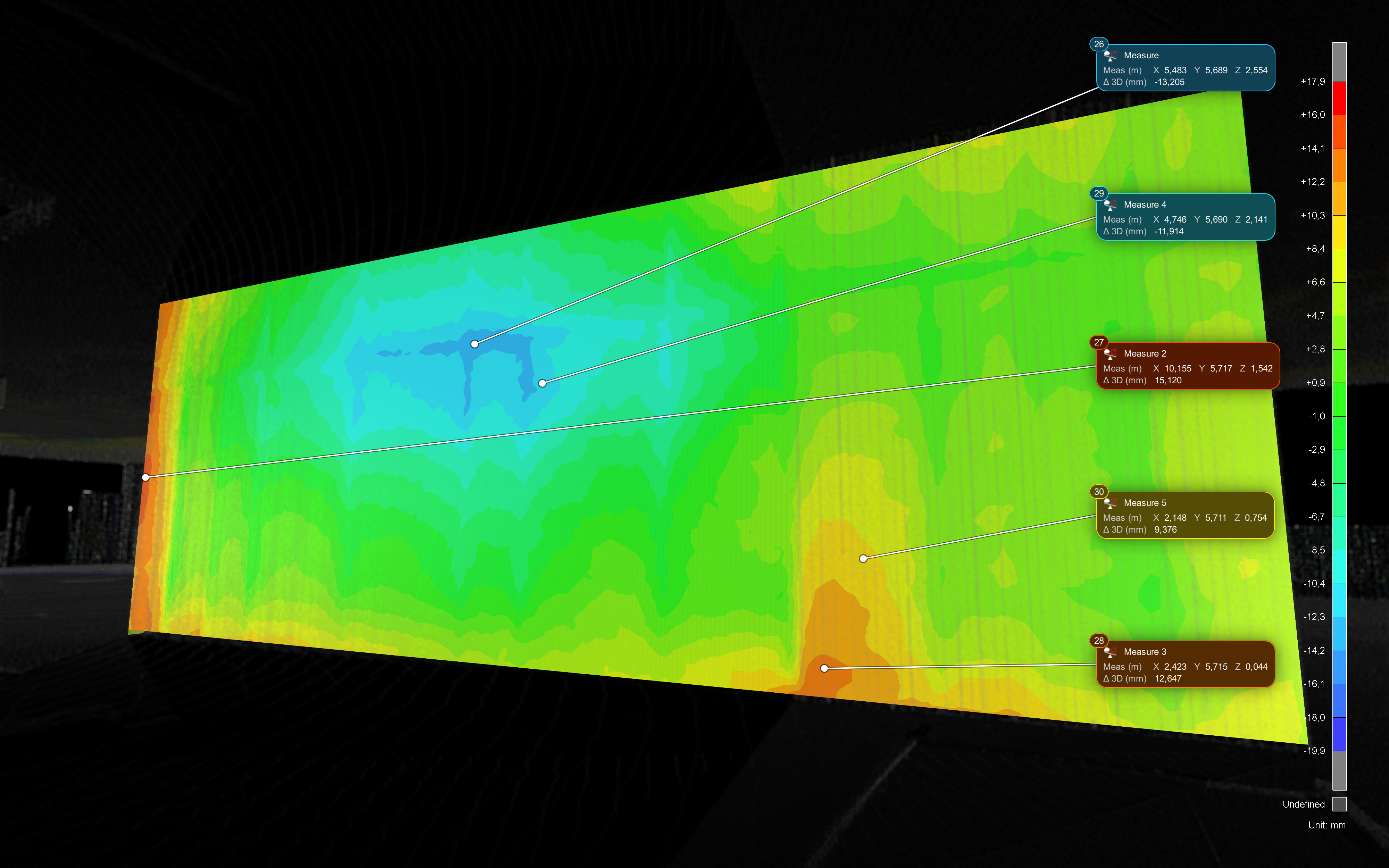
The contents of the new measures are revamped and completed with additional and flexible information. The composition of the measurements depends on the type of information that the user is looking for.
-
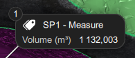
General contents: Measure ID, Icon, Header, Comment
-
Specific values: coordinates, deviation, volume, …
Some examples are presented in the table below.
|
Diverse measures |
New style of measures |
|---|---|
|
Inspection |
|
|
Volume |
|
|
Distance |
|
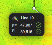
|
FF / FL Analysis |
|
|
Geometric object |
|
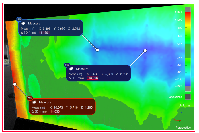
Better management of tolerance
When the color gradient is defined with tolerance values, the tolerance value is automatically adjusted to the gradient.
Position in the 3D Scene
The position of the new measures can be defined via two different ways:
-
The main settings for the next projects (screenshot above)
-
The contextual menu for the current project (right click in the 3D Scene)
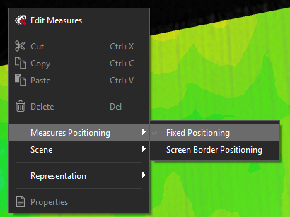
The next views can illustrate the two different positions.
|
Fixed Positioning |
Screen Border Positioning |
|---|---|
|
|
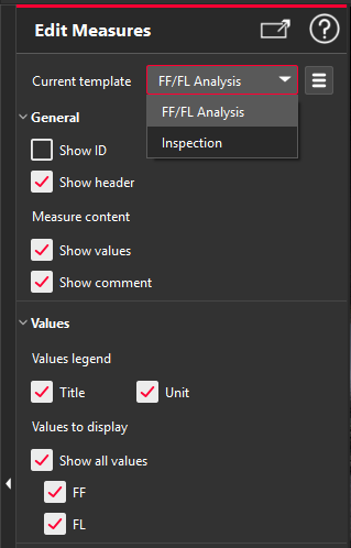
Template
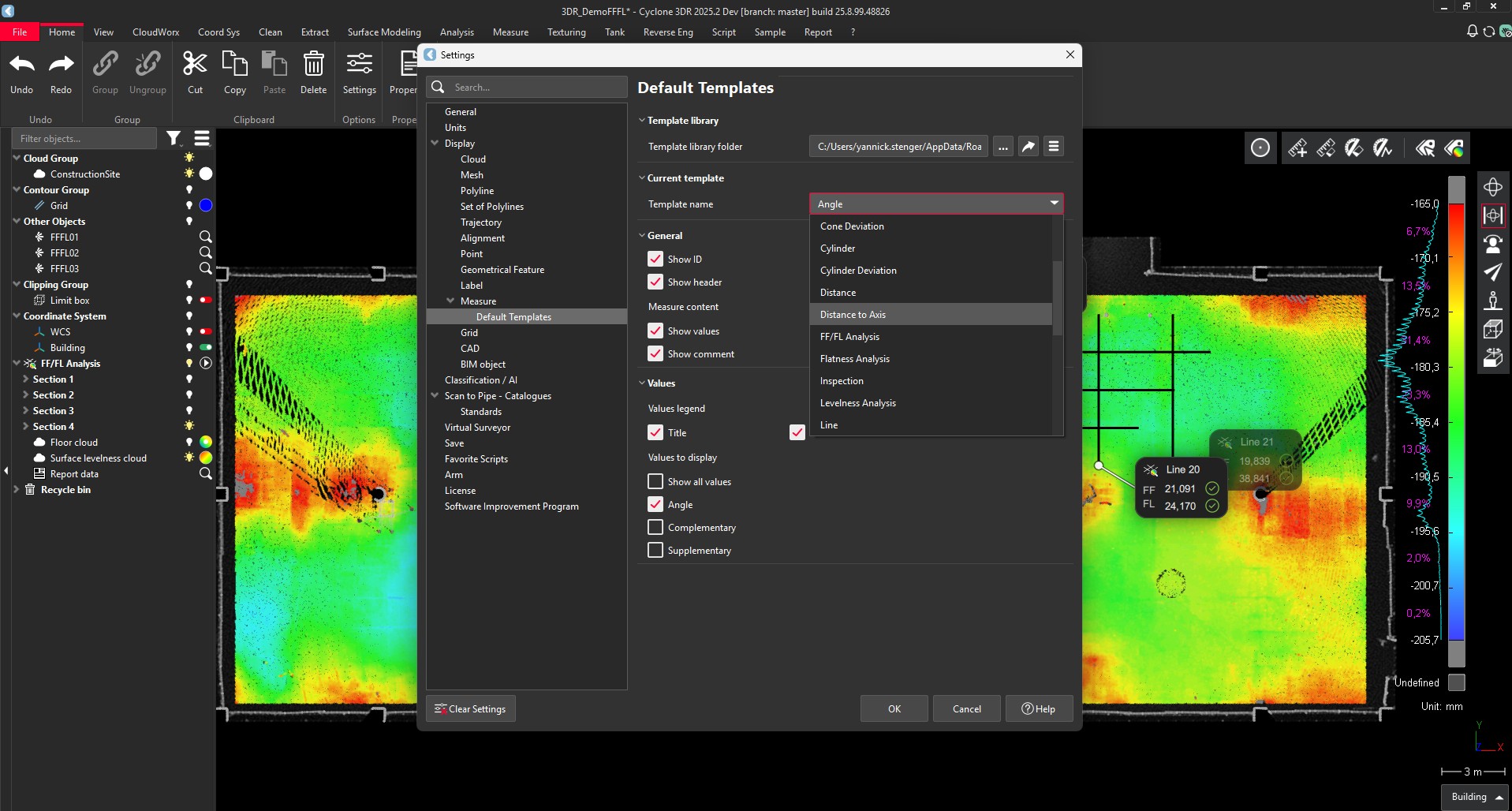
All the types of measure have a specific template. Templates can edited through Edit Measures or through the Main settings.
Whereas the Edit Measures function provides a fast way to edit only existing types of measures in the project, the main Settings window allows users to change the default templates of all possible types of measures in Cyclone 3DR 2025.2. Any changes will be applied to future projects and not to the current one (use Edit Measures from the Measure or contextual menu instead).
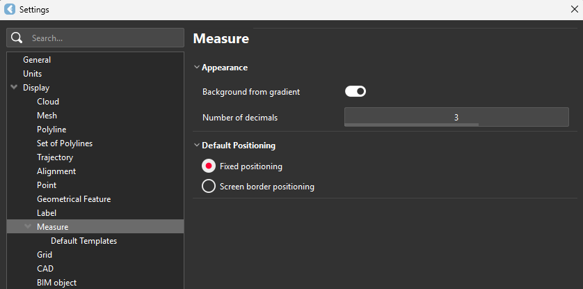
The “Default Templates” menu in settings offers a simplified experience where users can simply check or uncheck relevant measurement information.
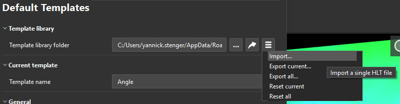
In addition, it is possible to export / save / restart the default templates of the Cyclone 3DR types of measures.
Using Home / Settings / Default Templates, any changes will apply to new projects and not to the current document or project (use Edit Measure in the Measure or contextual menu instead).
The parameters of the imported model replace those of the corresponding default model, which nevertheless retains its default name (ex: the custom settings for my ‘MyNewLevelnessAnalysis’ template will replace the settings for the corresponding default template, but its default name ‘Levelness Analysis’ will remain unchanged).
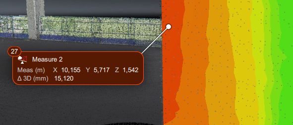
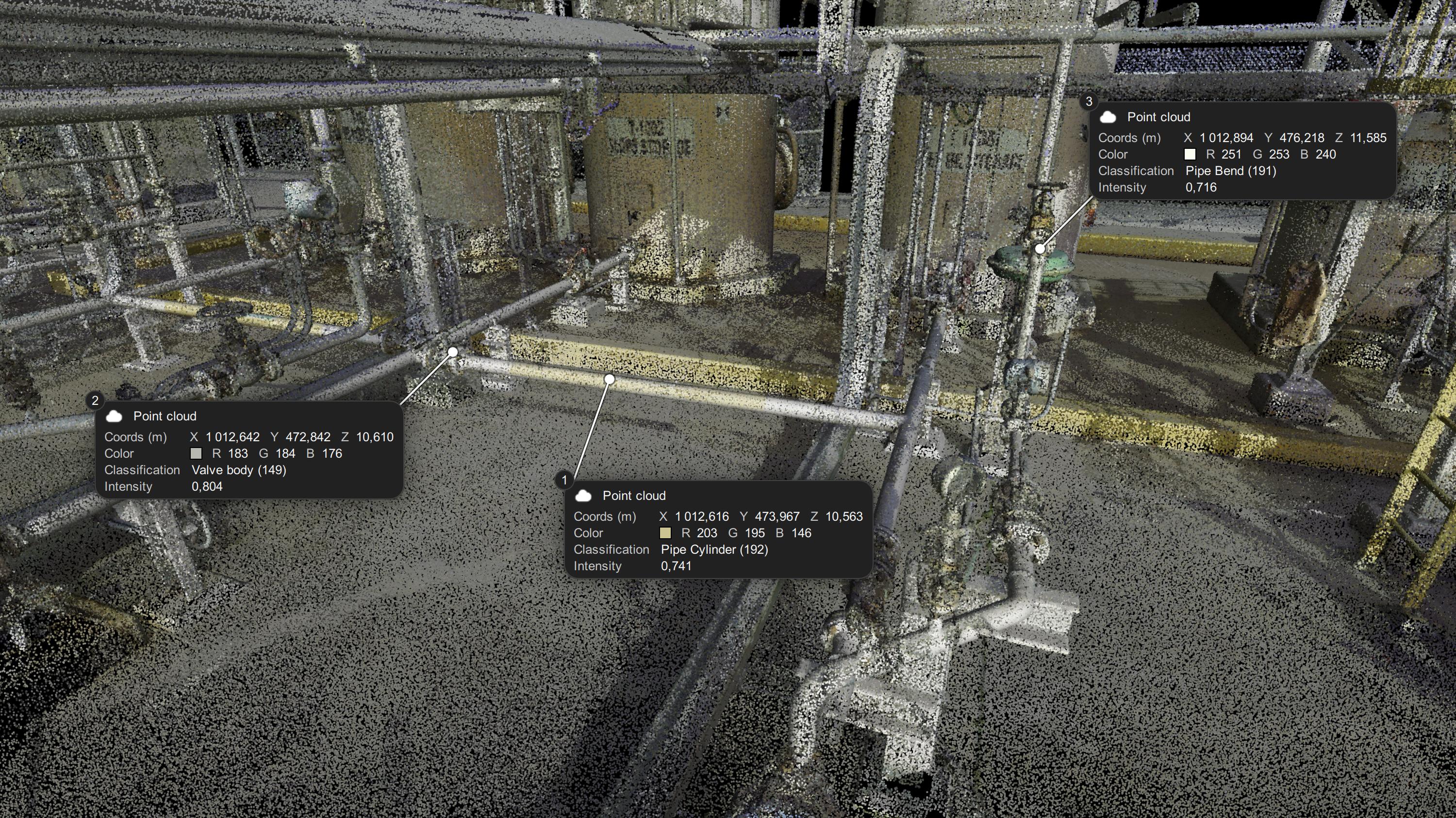
Pick Info
A new Pick Info feature is enabled in the Measure menu to extract information from any 3D asset with Cyclone 3DR 2025.2. The feature also works from the toolbar.
When the feature is activated, each click creates a new measure with the 3D Asset information:
-
For clicked point clouds, the measure returns information like coordinates, RGB, class, intensity value, return type, …
-
For geometric objects, the measure returns information like center coordinates, dimensions, vectors or coordinates.
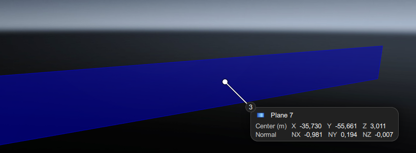
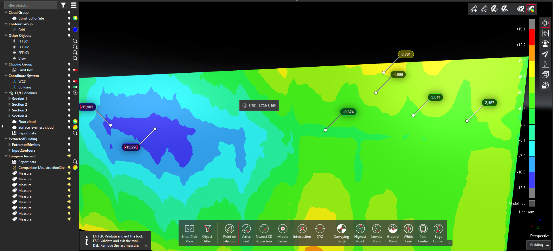
Pick Analysis
A new Pick Analysis feature is enabled in the Measure menu and in the toolbar. The feature replaces the ancient “Measure Deviation” feature and returns the analysis values (deviation, levelness, …) from the clicked object at the point coordinates.
Script functions
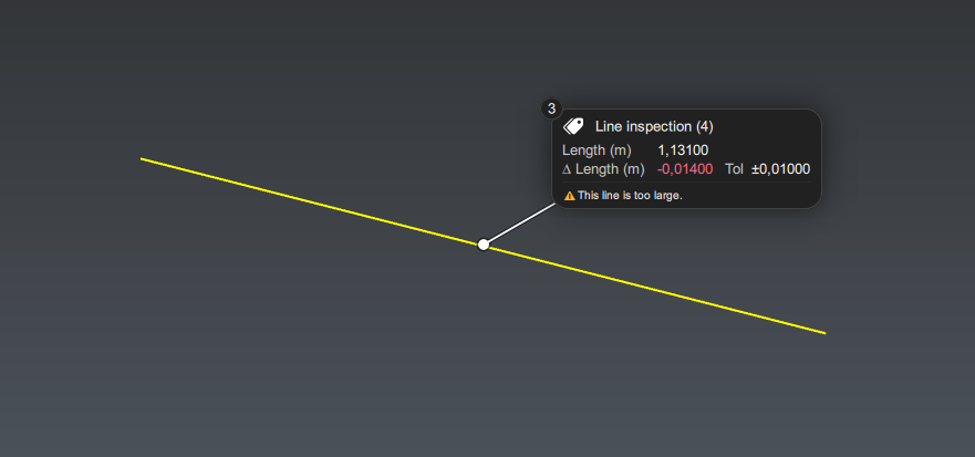
A new class SMeasure allows to create custom measure to cover advanced use cases.
Example of script code for a basic measure
In the example below, the function returns a measure that contains the length of a line.
let meas = SMeasure.New(Line inspection (${iLine.GetName()}), attachPoint, _counter++);

meas.AddRow({
    "key": "meas"+iLine.GetName(),
    "name": "Length",
    "unit": "m",
    "values" : [{
        "key": "meas"+iLine.GetName()+"_value",
        "value": length
    }]
});

let lineDiff = length - _lengthRef;
let tol = 0.01;
meas.AddRow({
    "key": "meas"+iLine.GetName(),
    "name": "∆ Length",
    "unit": "m",
    "tolMin": -tol,
    "tolMax": tol,
    "values" : [{
        "key": "meas"+iLine.GetName()+"_delta",
        "value": lineDiff
    }]
});
meas.AddToDoc();

if(Math.abs(lineDiff) > tol)
{
    meas.SetComment("⚠️This line is too large.");
}
Additionally, Cyclone 3DR GitHub page for scripts is populated with new scripts to create measure assets.
Temporary support of previous “Labels”
Labels coming from previous versions are still supported in Cyclone 3DR 2025.2, including the related script functions, to facilitate the transition from the previous architecture to the new one.
Measurement | New experience
Within Cyclone 3DR 2025.2, the measurement experience is deeply modernized with the purpose to improve the user experience and to give more capacities to users. The enhancements are detailed in this section.
This feature is available to users with all Editions of Cyclone 3DR, including the Viewer.
Settings
In the Measure group of the Settings, the user can adjust the main appearance parameters and the positioning of the measures.
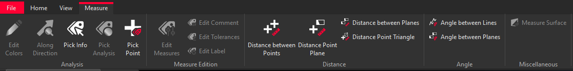
Menu
To give more visibility and to improve the user experience, a new Measure menu is created and many measurement tools are moved from the Analysis menu to the Measure menu.
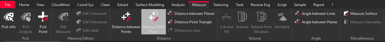
Toolbar
The toolbar is updated with quick access to
-
Pick Info
-
Pick Analysis

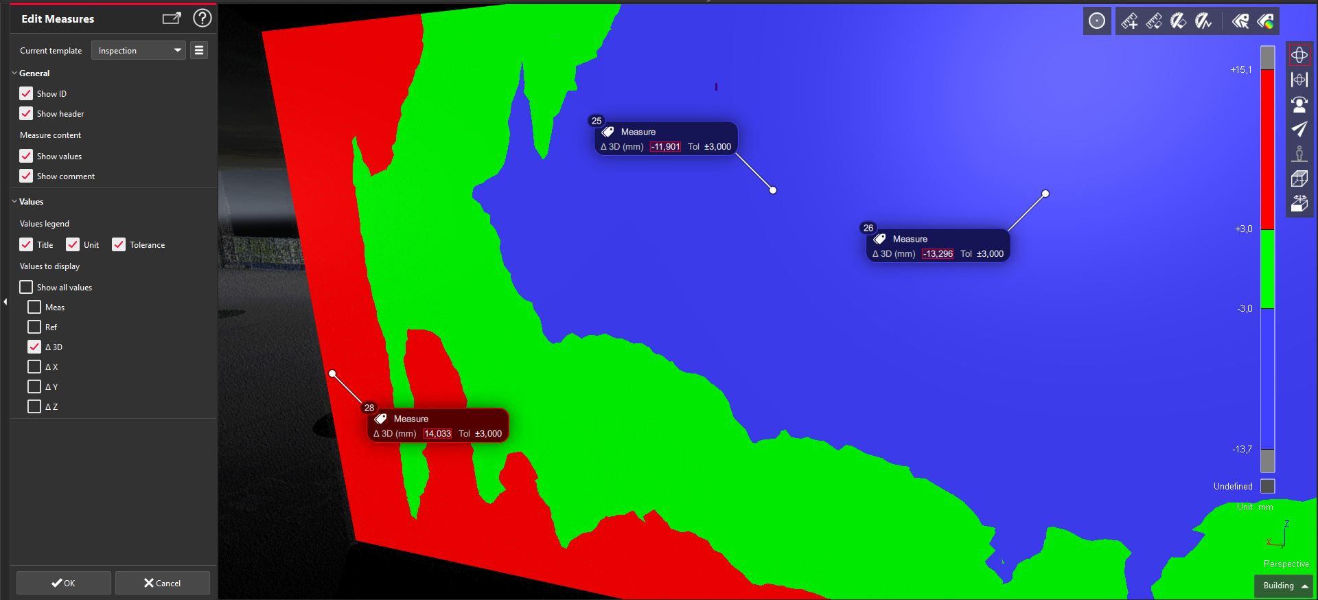
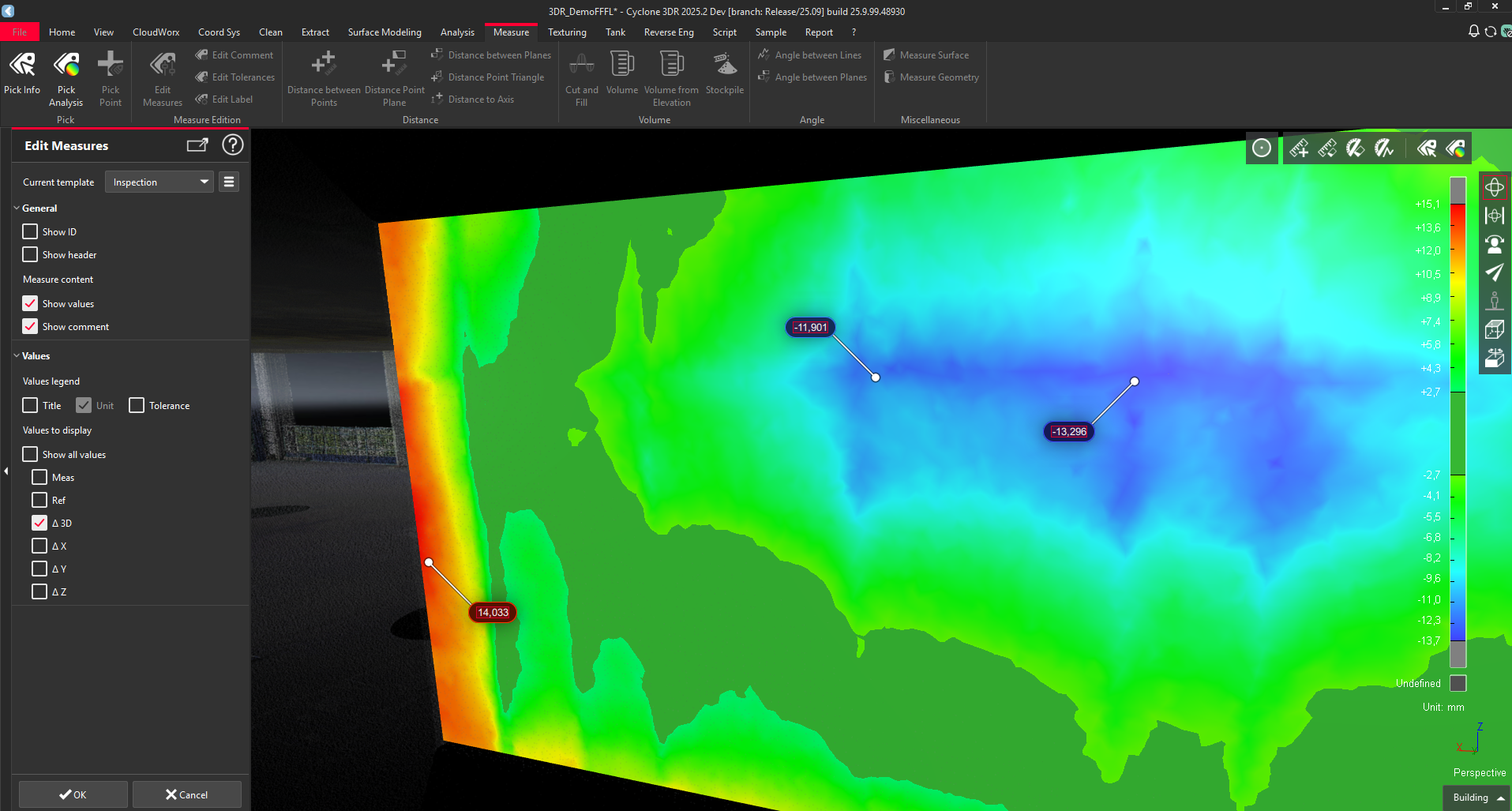
Edition
To edit measurements globally, a new command is exposed in the Measure and in the contextual menu (right click).
This command provides an easy way to customize the contents of the types of measures that already exist in the Cyclone 3DR project.
There are indeed a very wide panel of measures in Cyclone 3DR. To make it fast to use, the Edit Measurements function only allows you to modify existing measures in the project.
The new edit measures tool offers users the flexibility to adapt to a variety of project needs and customer requirements.
|
Detailed content of Inspection values |
Simple presentation of 3D Inspection values |
|---|---|
|
|
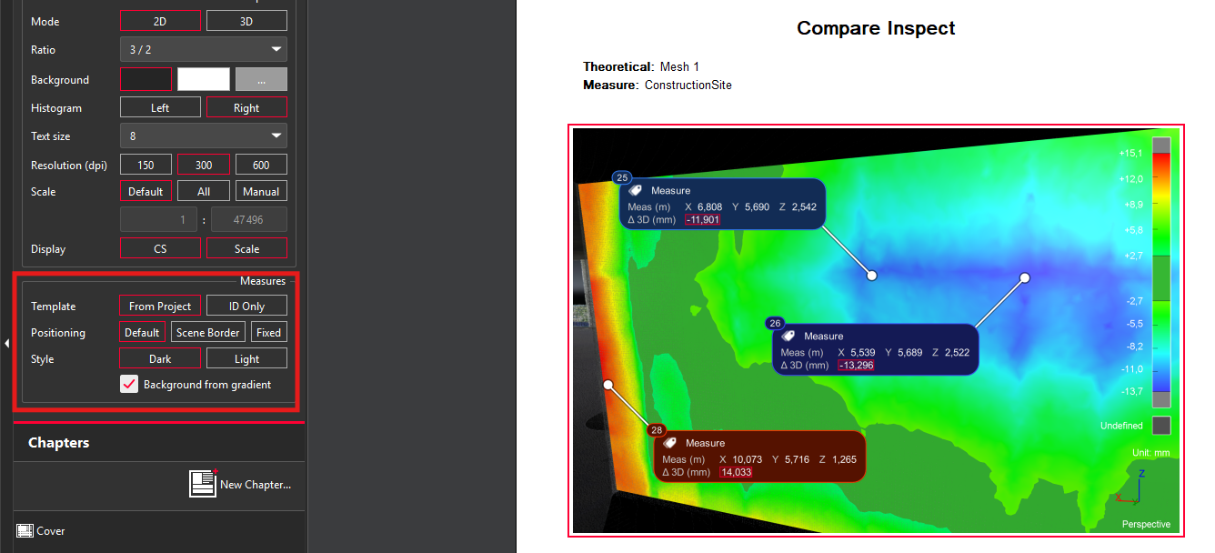
Report Editor
The report editor exposes new capacities to edit the display of measures for a selected viewset. It is possible to adjust:
-
The contents of the template:
-
all information from the current Cyclone 3DR project
-
measure index (ID) only
-
-
The positions of the measures:
-
Default (from the Cyclone 3DR project)
-
Scene Border
-
Fixed
-
-
The style: Dark or Light
-
Option to apply the color gradient for the background
Catalog fitting within Scan to Pipe
With Cyclone 3DR 2025.2, the Scan to Pipe workflow has been improved. The main new feature is the support of Catalogs and Standards, which helps to improve the efficiency and effectiveness of the entire “Scan-to-model” process.
This feature is available to users with the Plant or PRO licenses.
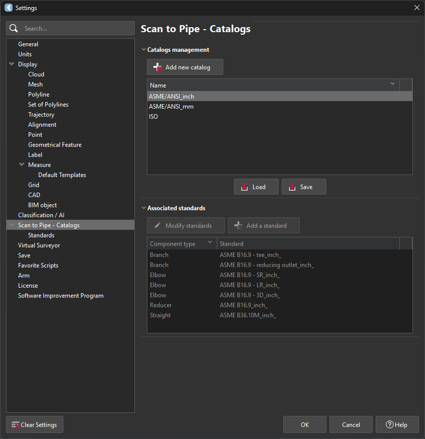
Catalog manager
Prior to starting a Scan to Pipe job with Cyclone 3DR 2025.2, it is recommended to verify and to complete if necessary the Catalog Manager.
Settings
|
Steps |
User Interface |
|---|---|
|
To access to Catalog Manager
First, the user must manipulate the catalogs. It is possible to:
|
|
From this section, it is possible to add a new standard and to visualize the imported ones. |
|
Default catalogs
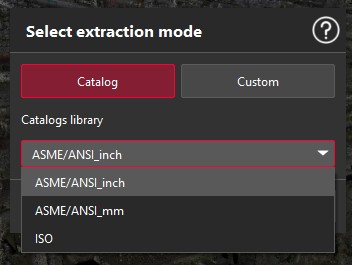
The embedded catalogs are the following ones in Cyclone 3DR 2025.2:
-
ASME/ANSI imperial (inch)
-
ASME/ANSI metric (mm)
-
ISO
Each catalog refers to a group of Standards that define the asset dimensions.
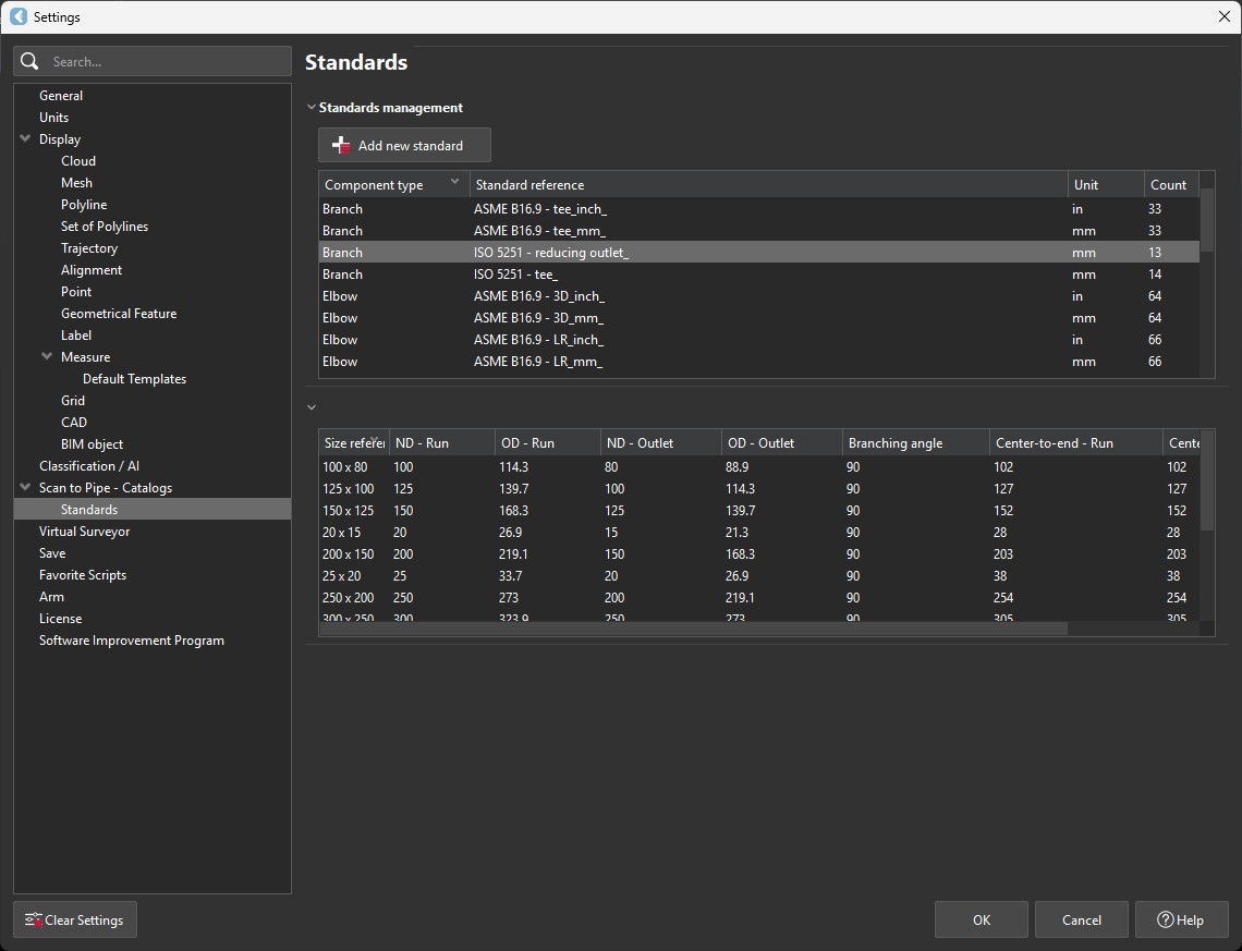
Standardized assets
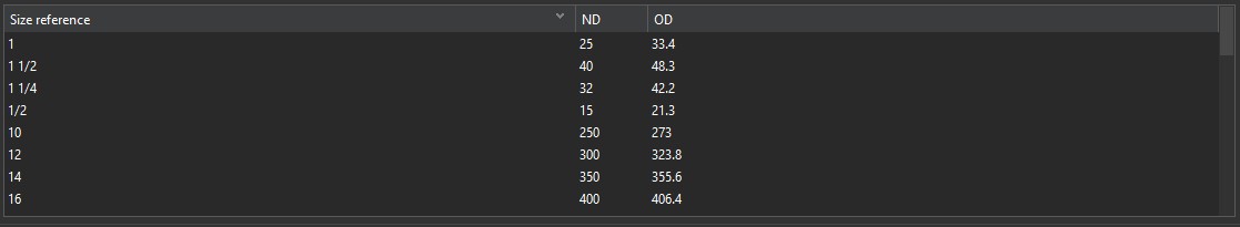
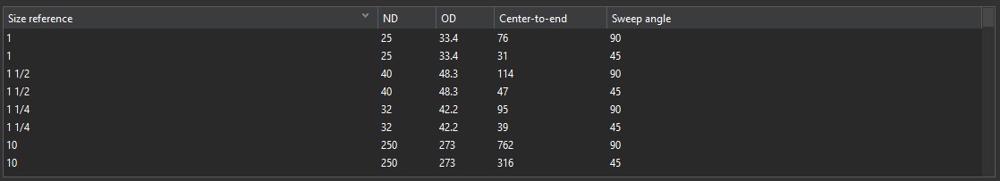
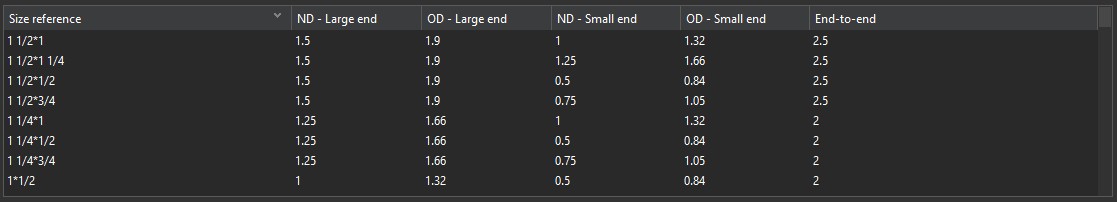
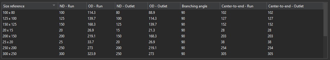
The piping assets that are compatible with Standards in Cyclone 3DR 2025.2 are: Straight segments, Elbows, Reducers and Branches.
|
Piping Asset |
Expected information in Standards |
|---|---|
|
Straight segment |
|
|
Elbow |
|
|
Reducer |
|
|
Branch connection |
|
Tutorial | How to add new catalogs and new standards?
The process to edit and to complete the libraries through the main settings is heavily detailed in the online documentation https://rcdocs.leica-geosystems.com/ and in the official YouTube channel https://www.youtube.com/@LeicaCyclone3DR. It is recommended to explore those resources.
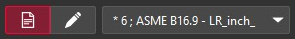
New experience
Start a project
To begin an extraction job, the process is unchanged: select the point cloud, go to Extract menu and execute Scan to Pipe. Then, a new experience is exposed.
|
Info |
Illustration |
|---|---|
|
Start a new project |
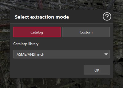
|
|
Choose the reference Catalog |
|
|
Model a Custom project without any references to a catalog |
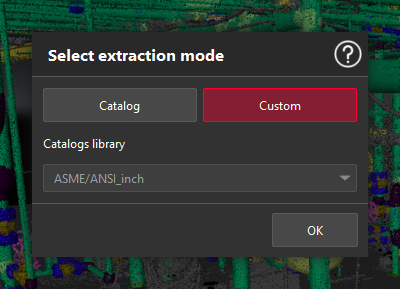
|
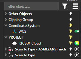
To show the difference between Catalog-driven Scan to Pipe jobs and Customized Scan to Pipe jobs, the name of the project is automatically defined and the icon is also different as illustrated below.
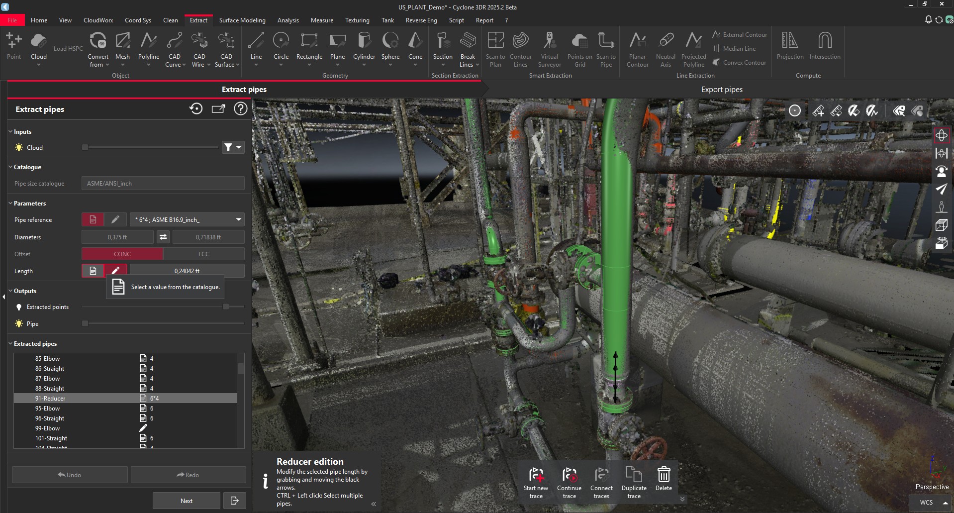
Extraction of assets
In Custom mode, the extraction workflow is unchanged.
In Catalog mode, the extraction banner is exposed with new possibilities to give users as much flexibility as possible.
The Catalog-guided extraction modes work according to the following table.
|
Extraction method |
Straight Pipes |
Elbows |
Reducers |
Branches |
||||||
|
Diameter |
Diameter |
Bend Radius |
Angles |
Diameters |
Combination of diameters |
Length |
Diameters |
Combination of diameters |
Lengths |
|
|
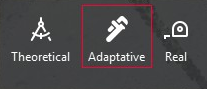
Theoretical |
Standards |
Standards |
Standards |
Standards |
Standards |
Standards |
Standards |
Standards |
Standards |
Standards |
|
Adaptative |
Standards |
Standards |
Standards |
Custom |
Standards |
Standards |
Custom |
Standards |
Standards |
Custom |
|
Real |
Standards |
Standards |
Custom |
Custom |
Standards |
Custom |
Custom |
Standards |
Custom |
Custom |
The next table explains how the different methods are available for the various extraction tools.
|
Tools |
Mode |
Theoretical |
Adaptative |
Real |
|---|---|---|---|---|
|
Auto-Extraction [Pipe Run] |
Create + Connect |
|
|
|
|
Elbow + Straight |
Create + Connect |
|
|
|
|
Reducer + Straight |
Create + Connect |
|
|
|
|
Straight pipe |
Create + Connect |
|
|
|
|
Flange |
Create + Connect |
|
|
|
|
Branch |
Connect |
|
|
|
During the extraction job, the user has the possibility to switch between methods, even for the same trace.
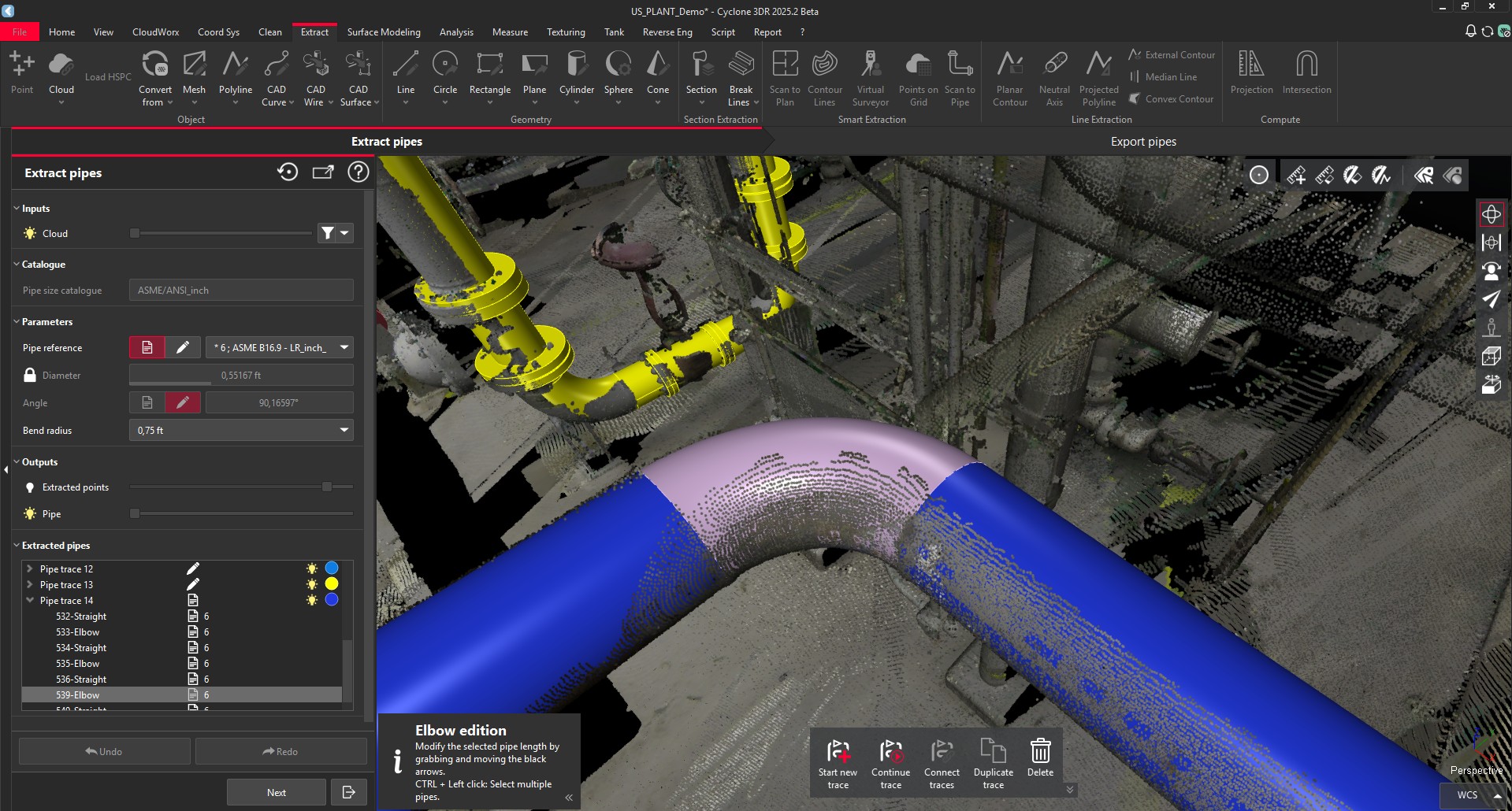
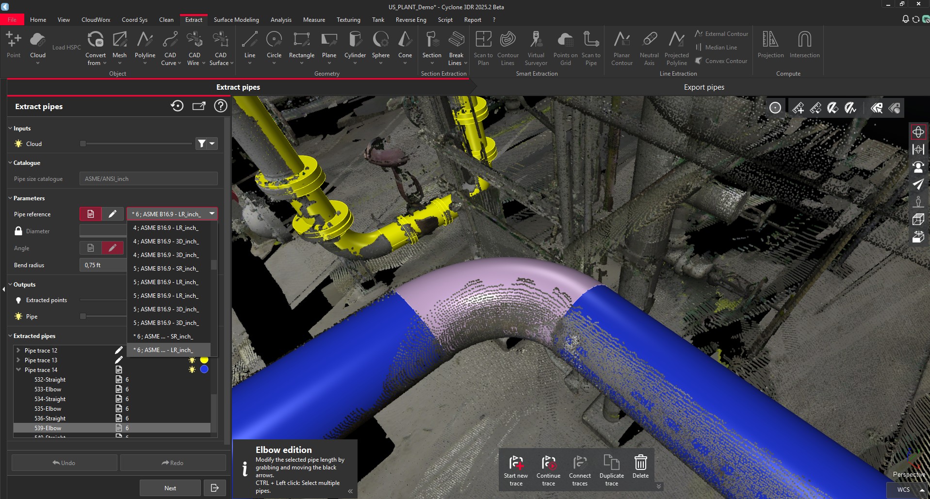
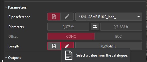
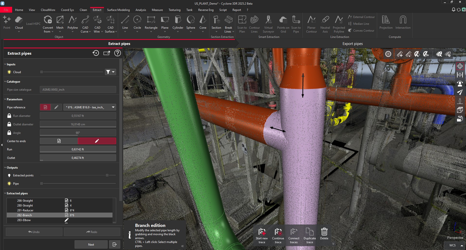
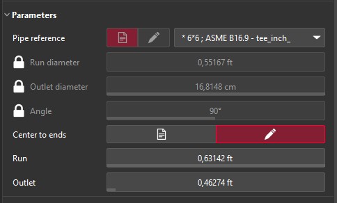
Editing assets
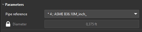
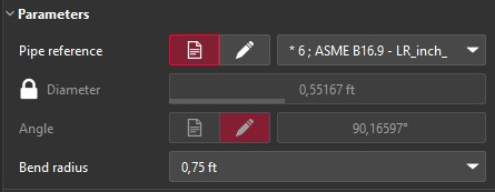
With the introduction of Catalog fitting, more possibilities are exposed to edit the assets according to Catalogs and Standards.
For Elbows, Reducers and Branches, the next option is exposed to give users the possibility to make adjustments.
|
Asset |
Command description |
|---|---|
|
Straight pipe |
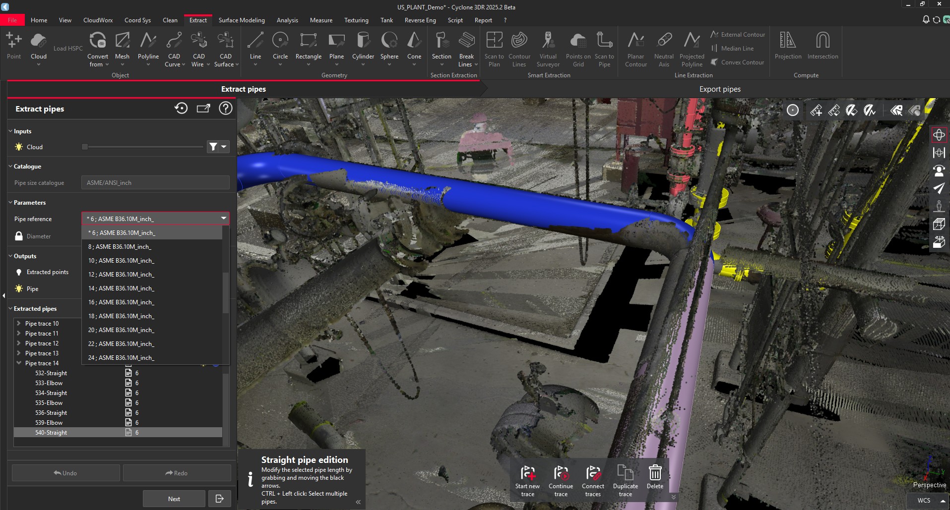
For straight pipes, it is not possible to switch from standardized parameters to customized ones in the Catalog extraction mode. The user has the possibility to create another Scan to Pipe project for the Custom mode extraction operations. |
|
Elbow |
|
|
Reducer |
|
|
Branch |
|
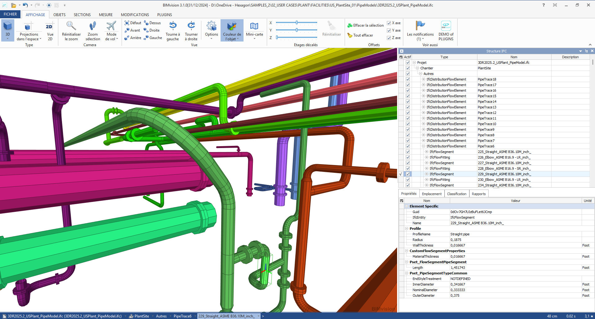
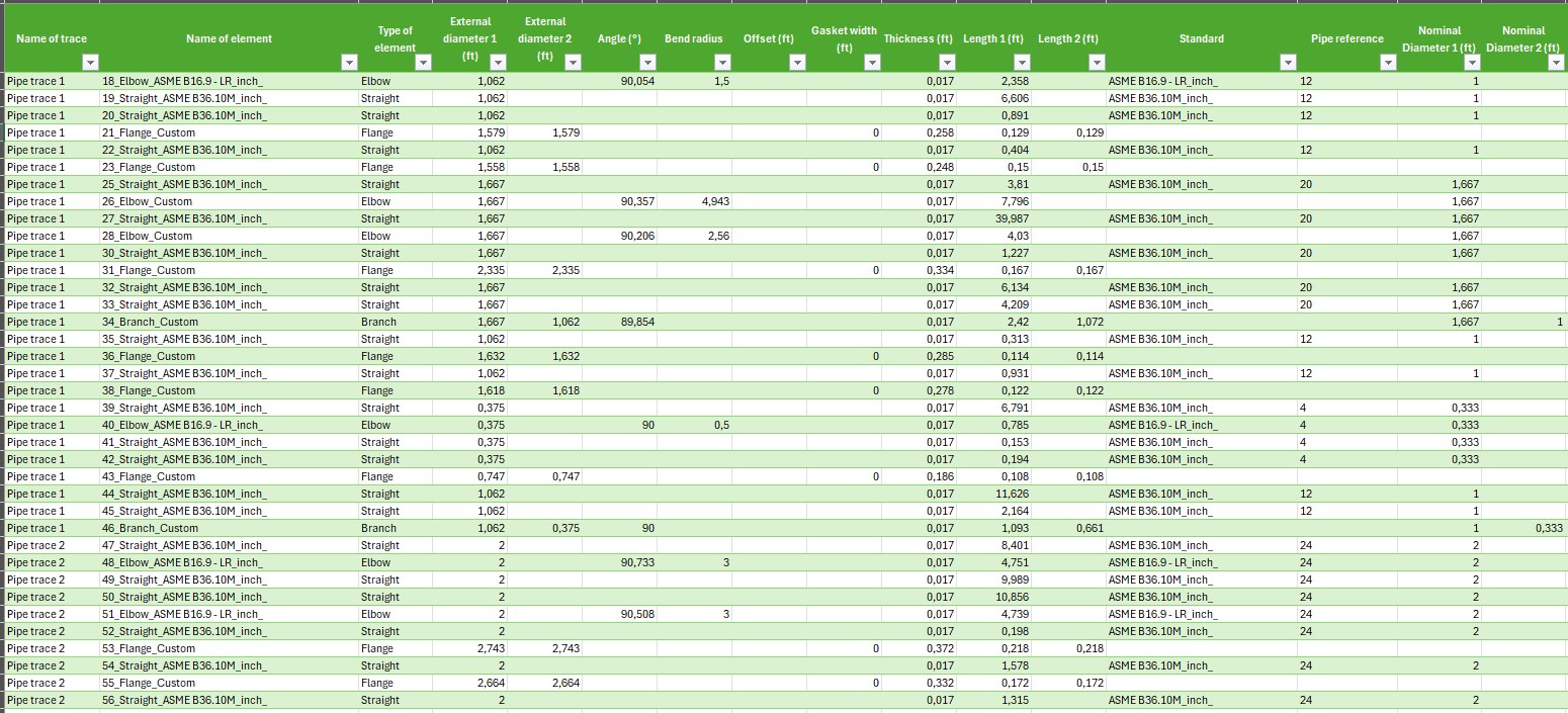
Export capacities
The Export command of Scan to Pipe function is unchanged. Thanks to the new Catalog fitting feature, the Catalog and Standard information is stored in the names of the exported models to IFC and COE or to the list of the piping assets to CSV.
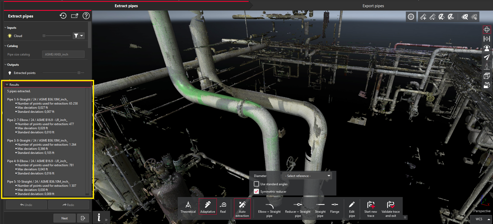
Feedback on fitting results
In addition to the pure Catalog-Fitting new capacity, Scan to Pipe is improved with the exposition of the fitting results with the following pieces of information for each extracted piping component:
-
Number of points used for extraction
-
Maximum deviation
-
Standard deviation
This feature is available for all types of extraction tools and for both Catalog-fitting and Custom-fitting modes.
Tolerance Checking
With Cyclone 3DR 2025.2, a new construction-industry-focused feature is released to complete the current panel of BIM Analysis toolset with Clash, Inspection Notes, Visual Notes or Progress Monitoring.
This feature is available to users with the AEC or PRO licenses.
The purpose of the Tolerance Checking is the comparison of a BIM model (IFC) and as-built conditions (point clouds in native Cyclone 3DR architecture) with the end-goal provide a report specifying for each component of the BIM model whether it is:
-
Done within Tolerance
-
Done out of Tolerance
-
Missing
Tolerance Checking enables the delivery of reports that can contain the following core information:
-
A one-page summary
-
A detailed collection of description for each analyzed component.
The targeted applications are the following one:
-
Tolerance verification according to contract or standard specifications
-
Verification of the completion of the works
-
Monitoring sub-contractors
-
Automatic Scan-to-BIM verification process
To keep a fluid user experience, Tolerance Checking is designed in a very similar way to Progress Monitoring. The similarities include:
-
Inputs must be:
-
A point cloud (LGSx or Reality Cloud Studio ones must be converted)
-
A BIM model from IFC format
-
-
For the best and most relevant results, edit the BIM model by creating sub-models to group similar assets prior to launching the workflow:
-
For example, tolerances for piping and columns differ and a separate analysis will yield the best results.
-
-
The results can be optionally optimized with the AI-model “Indoor Construction Site”:
-
As soon as the input point cloud is classified prior to the workflow, the option is exposed.
-
It has to be classified with the same version of Cyclone 3DR with the Indoor Construction Site model.
-
This optimization offers a refined assignment of the points and the main classes of the BIM model.
-
It does not impact the time performance of the computation.
-
-
Tolerance Checking is a 3-step workflow with similar steps:
-
Analyze, for the definition of the computation parameters.
-
Check, for a manual verification of the results BIM object by BIM object, with the capacity to visualize individual results, to navigate through an filtered list or to edit the tolerance status of the object if necessary.
-
Report, for an advanced preparation of the PDF report or the exported BCF ticket.
-
To execute the workflow, the user must select the point cloud and the BIM model, then run the new Tolerance Checking feature in the Analysis menu.
Step 1 - Analyze
Different parameters are exposed to the user.
-
Tolerance:
-
This tolerance parameter is the most important and must be defined by the user according to the requirement of the analysis to achieve.
-
The tolerance parameter is dynamic meaning it can be changed without relaunching the calculation. When the tolerance value is changed, the red/green color gradient adjusts automatically. This allows for a quick visual inspection of the intermediate results and easy adjustments before the workflow is completed. The tolerance parameter is also dynamic in the Check step of the workflow.
-
-
Exclusion zone:
-
This parameter gives a way to the user to remove the far points from the model and prevents him from pre-cleaning the data.
-
-
Coverage minimum:
-
This parameter is inspired from the Progress Monitoring experience.
-
The user must set a minimum value to define the coverage of each BIM object by the point cloud. During the computation, the coverage of each BIM asset is calculated and as soon as the minimum coverage is reached, the object is defined as installed (within or out of tolerance).
-
-
Optimize with indoor construction site classes:
-
Described above, this optional parameter can optimize the results and is recommended.
-
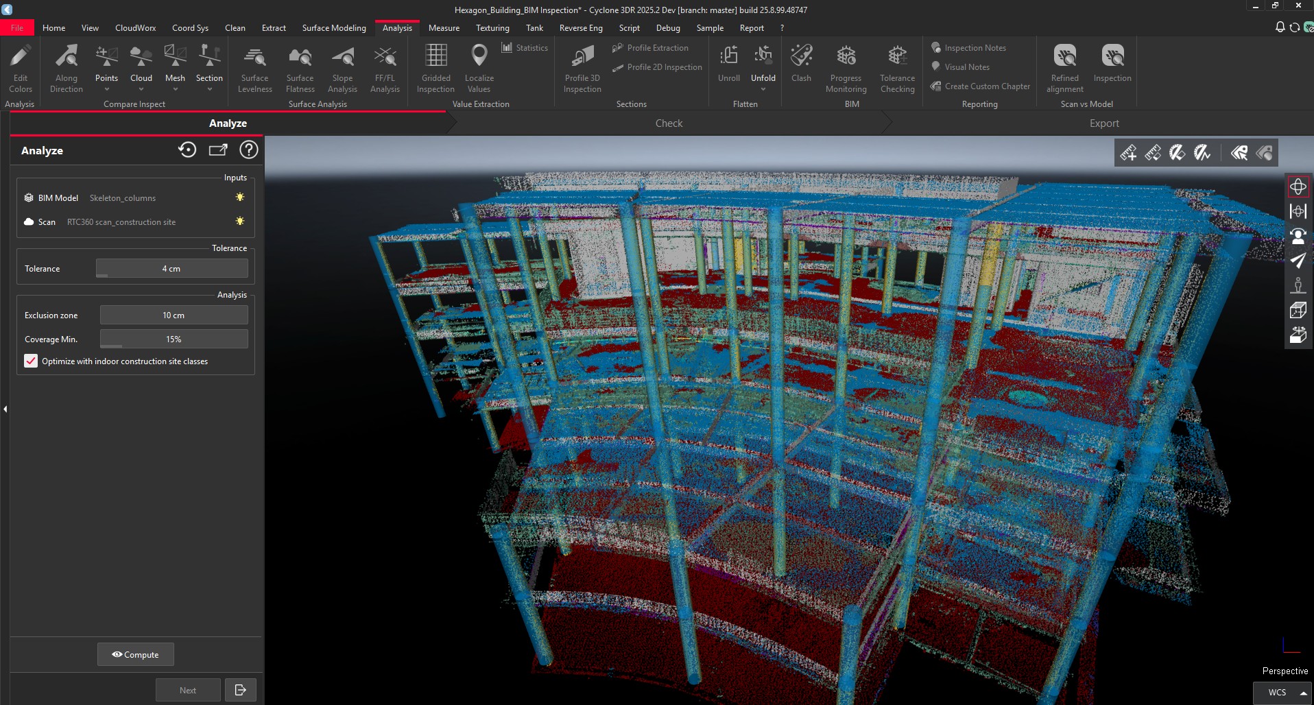
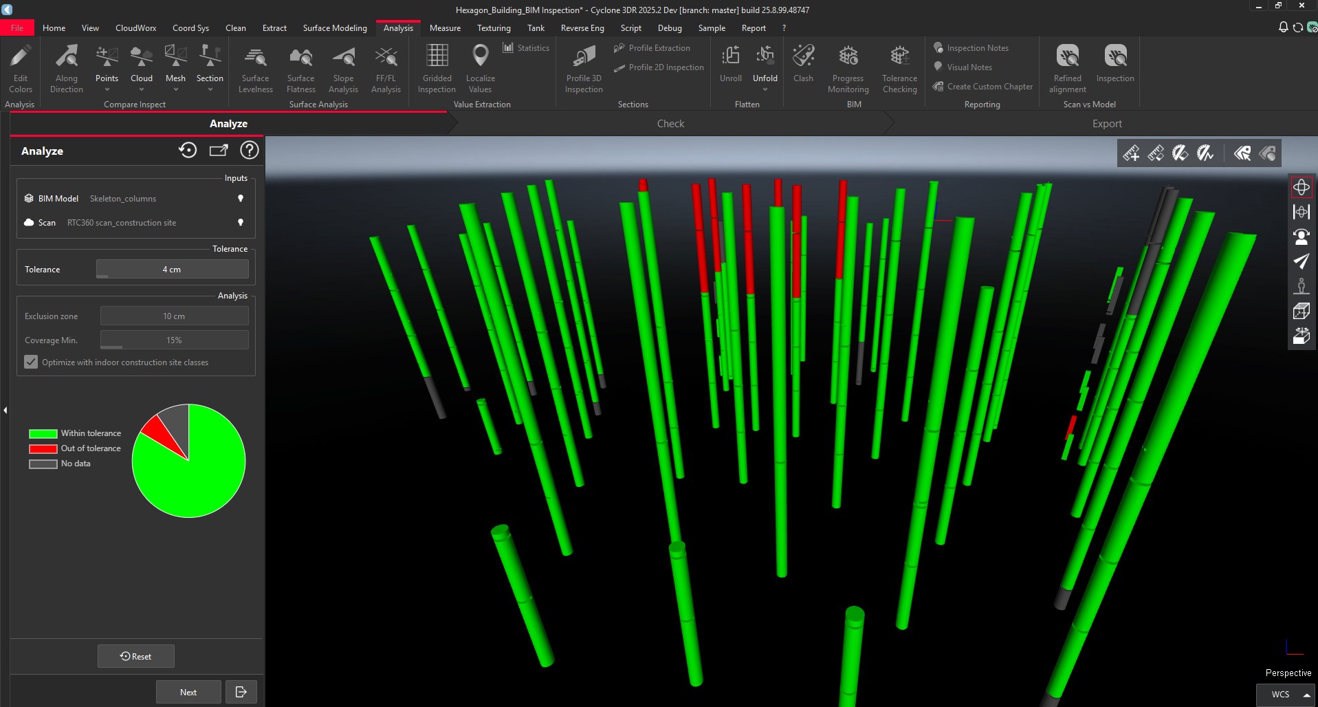
Once the parameters are defined, click on Compute to execute the analysis. Immediately, a distribution chart is visible to expose the first trend of the results. At this step of the workflow, the user can change the dynamic Tolerance value if necessary.
Step 2 - Check
Like Progress Monitoring, the dialog shows the list of the analyzed BIM objects. They are categorized in three groups:
-
Done within Tolerance – Green
-
Done out of Tolerance – Red
-
Missing or No Data – Grey
The user has the capability to toggle on/off the visibility of the BIM assets in the list and in the 3D scene with the filter widget. This option can facilitate the verification process, in particular when the user just wants to focus on the “out of” tolerance objects.
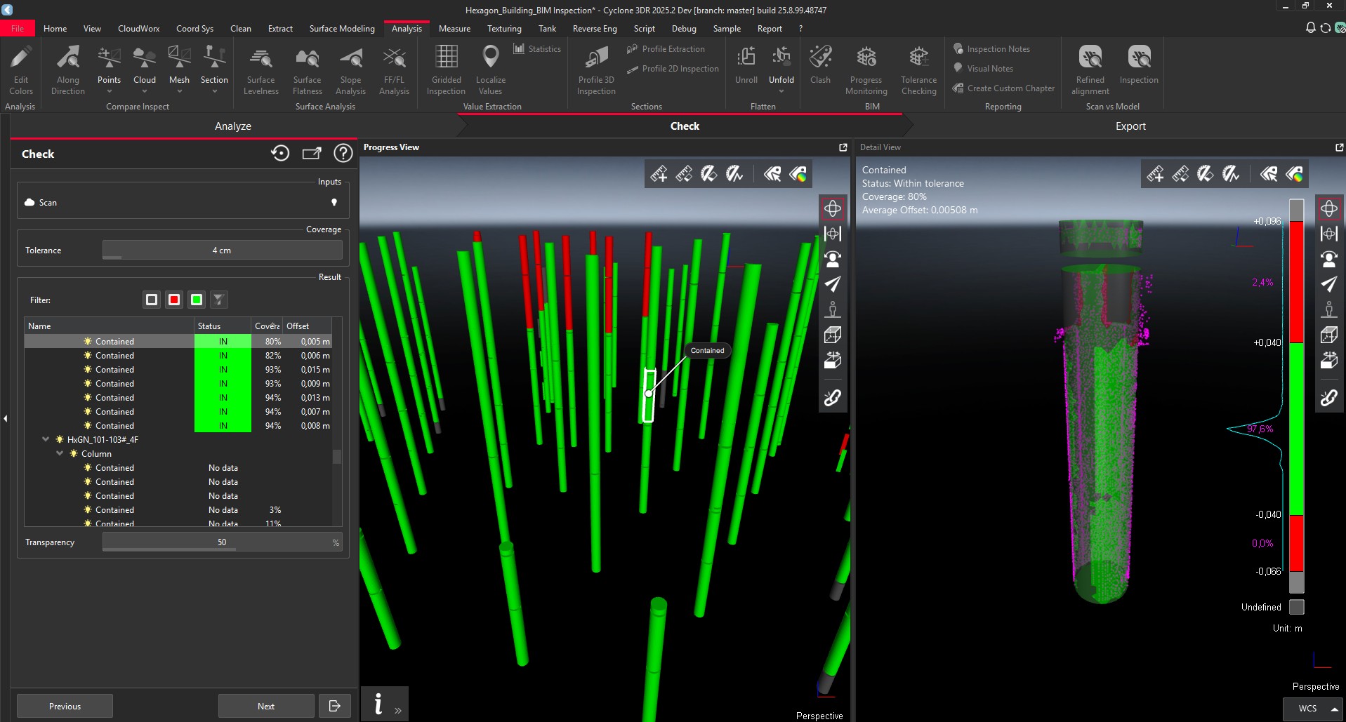
In the left part of the 3D Scene, the user also has the possibility to select a BIM Object with a click.
When an object is selected in the 3D Scene or from the list, the tolerance view panel on the left is zoomed on the selection and the results of the analysis are displayed in the detail view panel on the right, to give user all the relevant information for a deep reviewing process. The right screen shows:
-
The color gradient and the percentage distribution.
-
The sub-selection of the point clouds considered for the computation (purple).
-
The inspected and colorized BIM object.
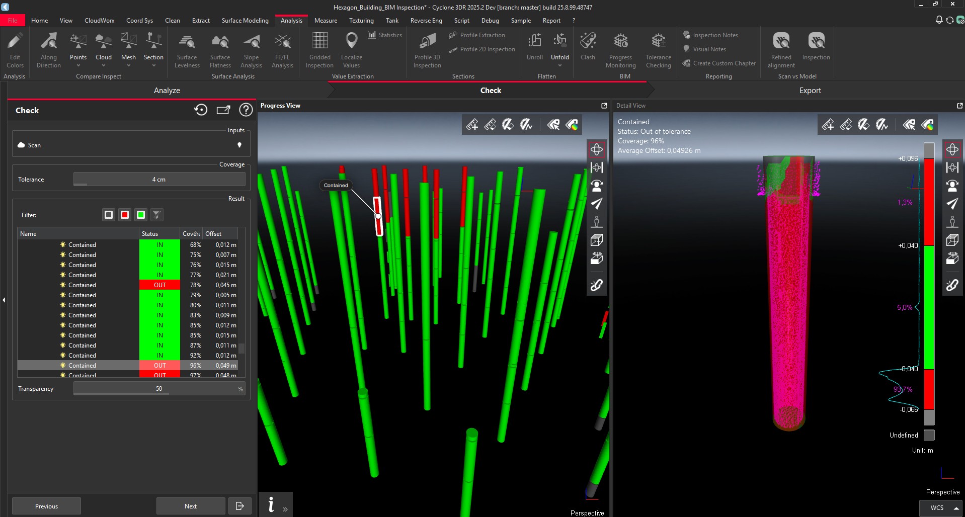
If the user wants to change the Tolerance status, he just has to click on the Space bar. Combined with the top/bottom arrows of the keyboard, it is possible to review all the BIM assets with efficiency.
Step 3 - Report
This part of the workflow gives users the tools to prepare their report.
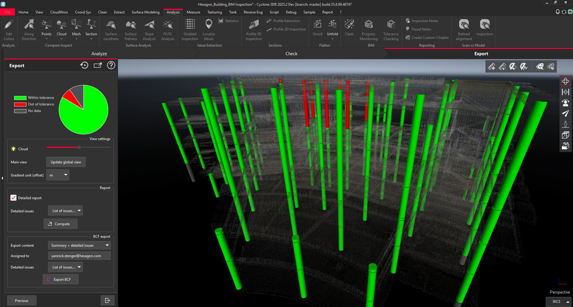
Recap of the results
At the top of the dialog, the updated distribution of the analysis is displayed.
View settings
In this section, it is possible to:
-
Adjust the transparency of the input point cloud
-
Update the main view of the report
-
Define the unit that will be exposed in the report. In spite of the fact that “meter” could be the project unit, it could make sense to display results in “centimeters”.
Report
Like Progress Monitoring, the “Detailed Report” is exposed and offers a way to create advanced report and a collection that contains for each analyzed BIM asset a presentation page with individual results, location, parameters and different views showing the analysis.
It is possible to filter which type of objects are part of the detailed report according to their tolerance status. For example, a sub-selection of the out of tolerance assets is usually appropriate to reduce the size of the report and to focus on the areas to double check.
A click on Compute is required to create the detailed part of the report because it leads to many additional screenshots and pages (proportional to the number of assets), so the time of computation could be long.
BCF Export
This part of the workflow is unchanged from Progress Monitoring and it is possible to export a BCF file that can contains many pieces of information.
BCF format is recommended for a pure BIM collaborative workflow to share the results with other stakeholders.
BCF export can include:
-
A single issue that summarizes the Tolerance Checking report
-
Multiple issues in addition to the summary with one additional issue for each BIM Object (up to the user selection among In Tolerance / Out of Tolerance / Missing). It is relevant to select the Out of Tolerance assets only for example
Ensure the "assigned to" field is filled to facilitate the BCF workflow process and that issues will be correctly assigned in the destination software application for the BCF file.
Report Editor
Once the report settings are defined, it is possible to quit the workflow and to go into the Report Editor.
The finalization of the report is similar to any Cyclone 3DR analysis and the user can adjust the report parameters based on their interests and the project specifications and publish a PDF file.
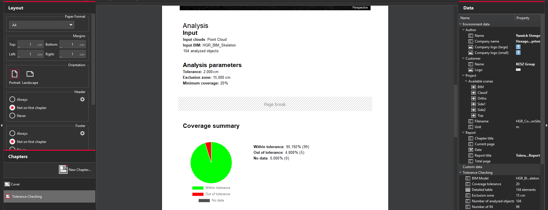
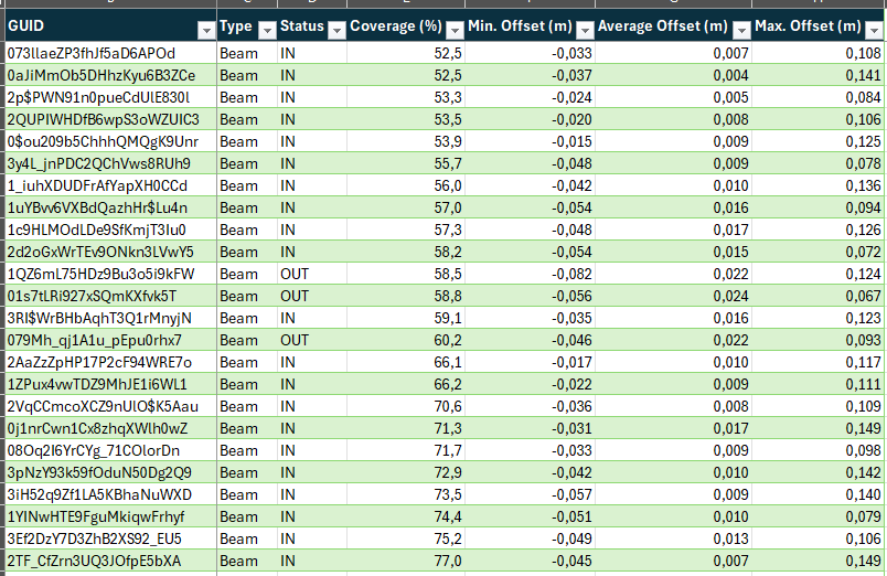
In addition to PDF and like Progress Monitoring, it is possible to generate 2 types of tables (as part of the PDF report or directly to CSV files):
-
Summary of the analysis: a simple table is by default created in the PDF report to gather the high-level information of the analysis and to present and sort the results by IFCtype.

-
Detailed table of the analysis: a complete table can be also extracted and can expose the result for each analyzed BIM object, showing information like the GUID identifier for example. This type of export is to way to address advanced workflows.
Unfold point cloud along polyline
Cyclone 3DR 2025.2 has a new Survey-industry feature: “Unfold Cloud” gives the capacity to unfold a selected point cloud along a polyline.
This feature completes the possibilities for traditional surveying workflows or for Heritage applications or for various renovation use cases:
-
Facade drawing
-
Orthoimage creation
-
Curve surface analysis
-
Area measurement
-
…
To start the workflow, the user must have:
-
A point cloud
-
A polyline, that has been extracted, drawn along the point cloud to analyze. The position and the orientation of the polyline are key to define the process.
Tip
-
Use Scan to Plan to create the polyline that will guide the unfolding process of facade use cases.
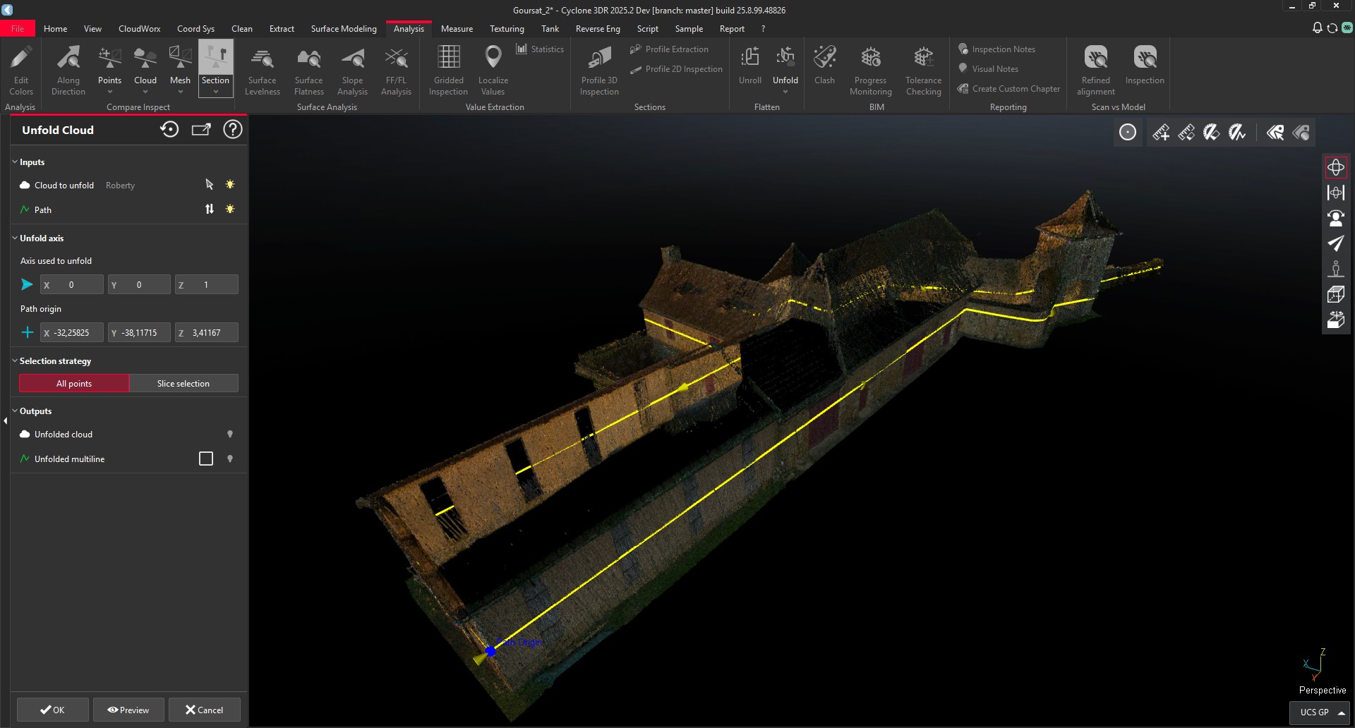
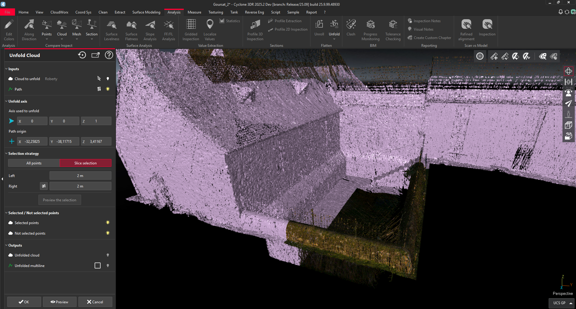
Within the feature, the main parameters are the following ones:
Polyline settings:
-
The axis that defines how the point cloud will be unfolded. The default value is the vertical Z axis, which fits to the large majority of the use cases.
-
The origin of the polyline. This option is important when the polyline is closed and the user might want to change the origin of the project.
The selection strategy:
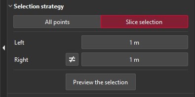
-
This toggle lets the users define if he wants to extract the entirety of the points during the creation of the unfolded data, or if they want to extract a portion of it.
-
With multiple objects, multiple buildings, multiple facades, it is recommended to toggle on the “Slice Selection” mode.
-
When the “Slice Selection” mode is toggled on:
-
The user can decide the width of the temporary slice that will be used to keep the points projected on the output, the unfolded point cloud.
-
It is possible to have a symmetric slice along the polyline or it is possible to define different slice widths on the left and on the right of the polyline from view of the selected direction axis (quite often from the top).
-
It is required to click on “Preview the selection” and the points will be pre-selected and highlighted accordingly.
-
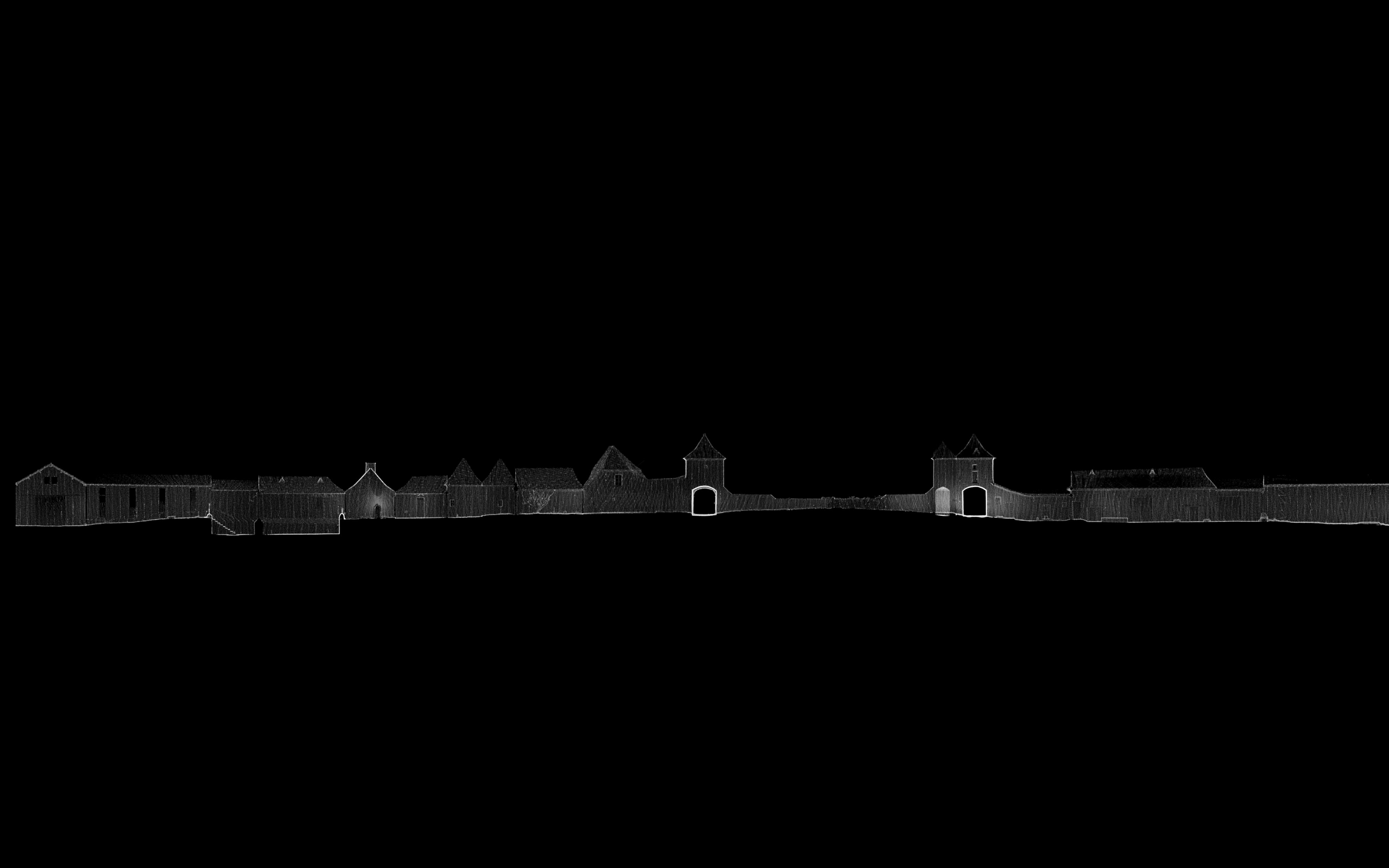
When the options and parameters are properly defined, a click on Preview computes the unfolding process and the unfolded point cloud is immediately displayed in the 3D Scene.
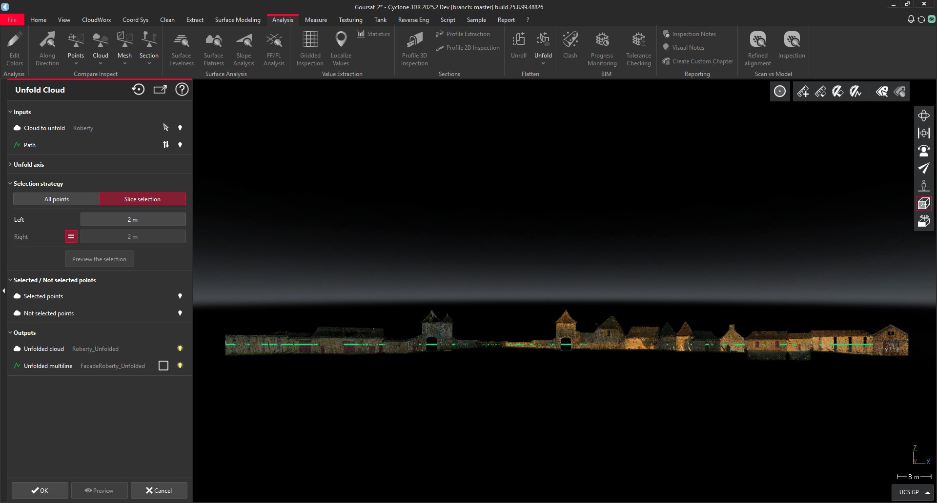
After quitting the feature, the user gets an unfolded point cloud and he can proceed to the final part of the Cyclone 3DR job like drawing, measuring or orthoimage creation for examples.
This feature is available to users with the Survey or PRO licenses.
Point Cloud Classification updates
Updated engine
A new version of the Point Cloud Classification engine is deployed within Cyclone 3DR 2025.2. This update will unlock the Auto-Classification feature for the latest Nvidia Graphics cards (GeForce RTX) that are compatible with NVidia CUDA toolkit 12.8.
The mechanism is unchanged. As soon as Cyclone 3DR is updated, running Auto-Classification for the first time requires the download of the relevant pre-requisites. Restarting the application is required.
New performance option
In addition to extending the use of Auto-Classification to the highest performing machines, the functionality now includes a new “Reduce computer memory impact” option. This possibility is not mandatory and is relevant to check for lower RAM capacity machines.
The computation offers a tiling approach in the back-end that barely impacts the quality of the point cloud classification process, and deploys a step-by-step computation of the selected point clouds. As a consequence, the time performance is slower (approximately + 30% longer) when the option is checked, but the consumed RAM memory is significantly reduced, which also reduces the occurrence of crashes.
New classification models
Two auto-classification models are updated within Cyclone 3DR 2025.2.
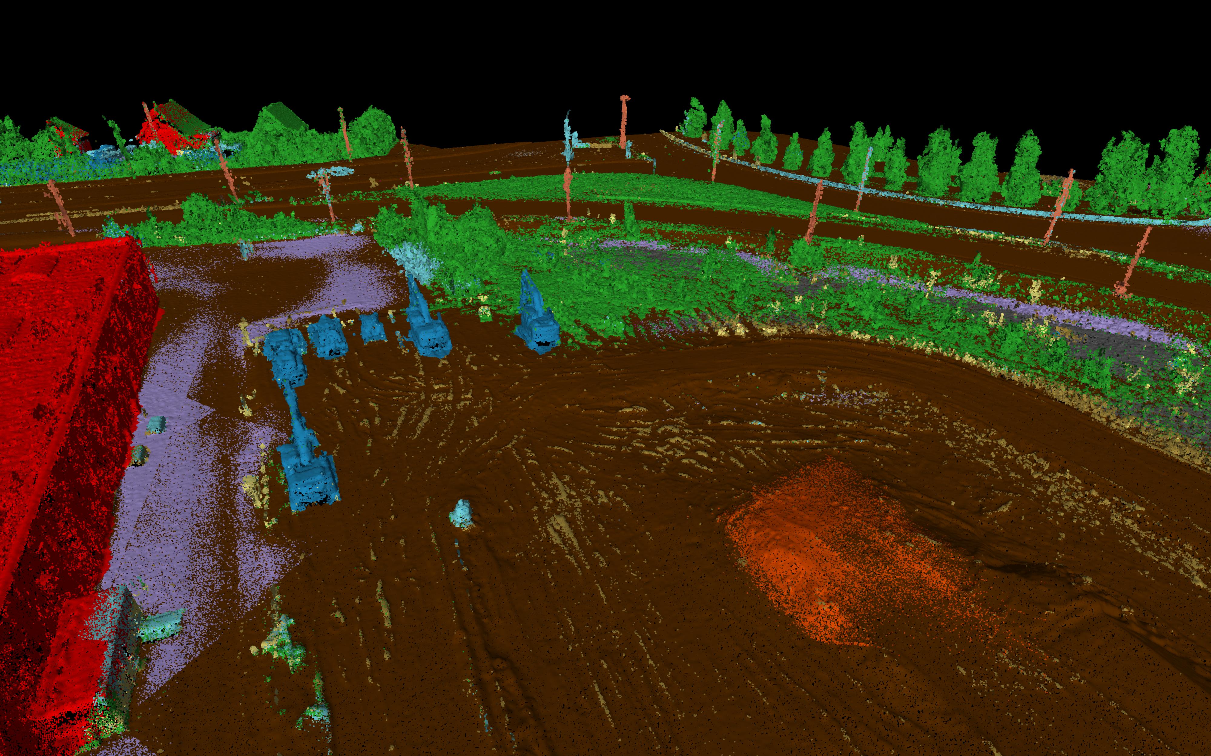
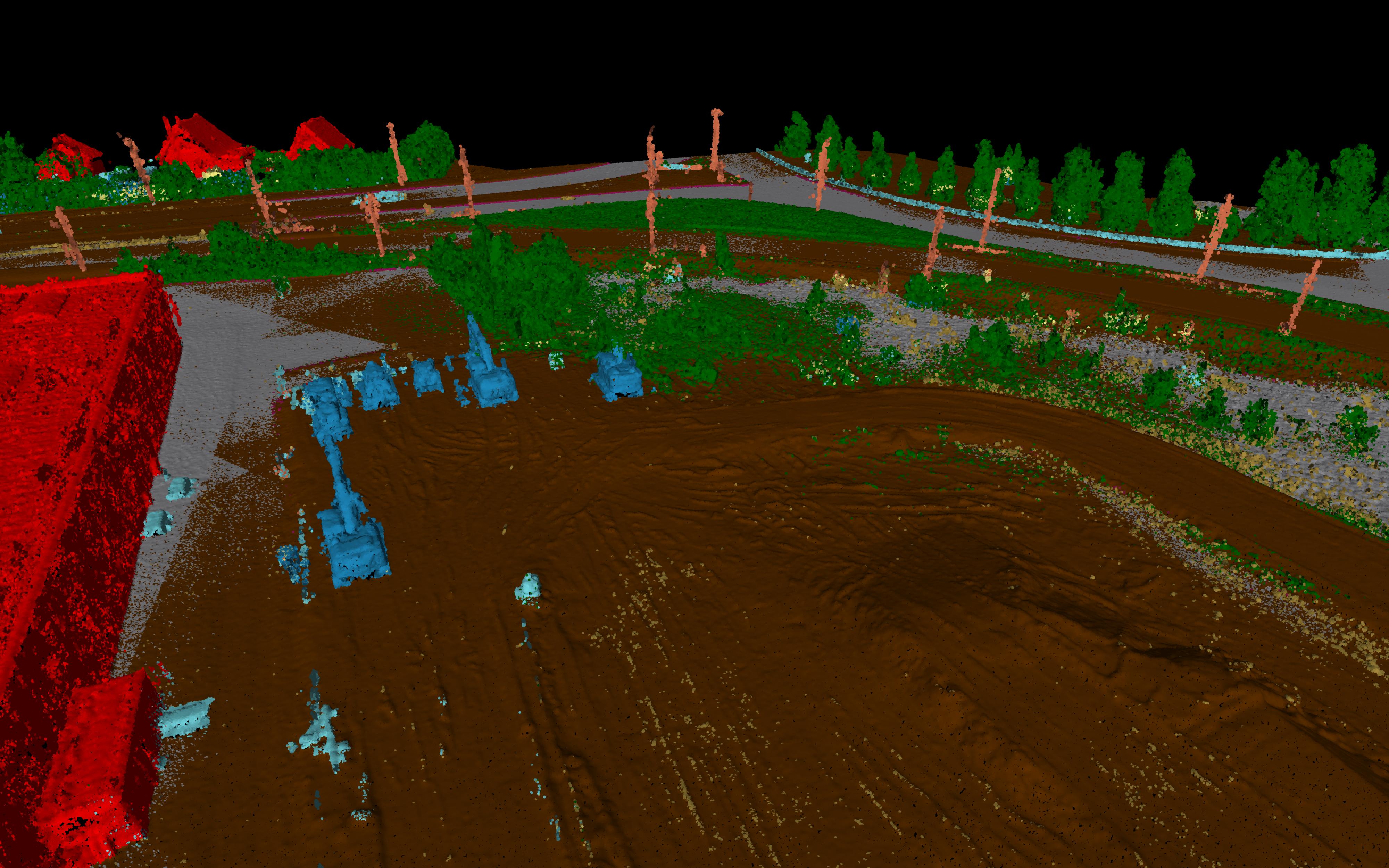
Outdoor Heavy Construction
This new version of the AI model is part of the regular updates of the feature. The main improvements are a better classification of stockpiles and of vegetation, improving accuracy in the segmentation of the data for Heavy Construction sites or similar environments.
|
Heavy Construction Model in previous versions |
Heavy Construction Model in Cyclone 3DR 2025.2 |
|---|---|
|
|
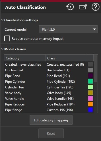
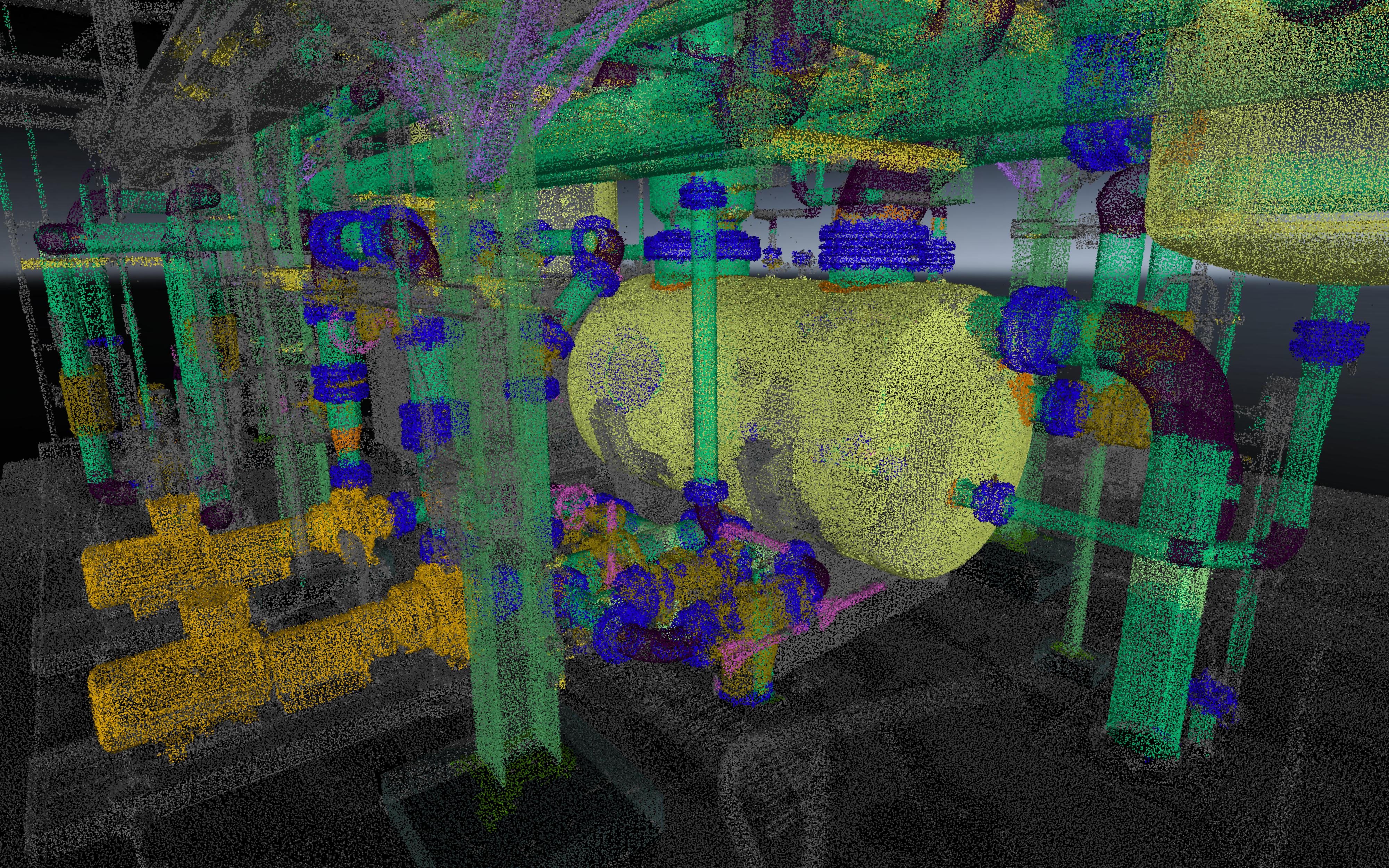
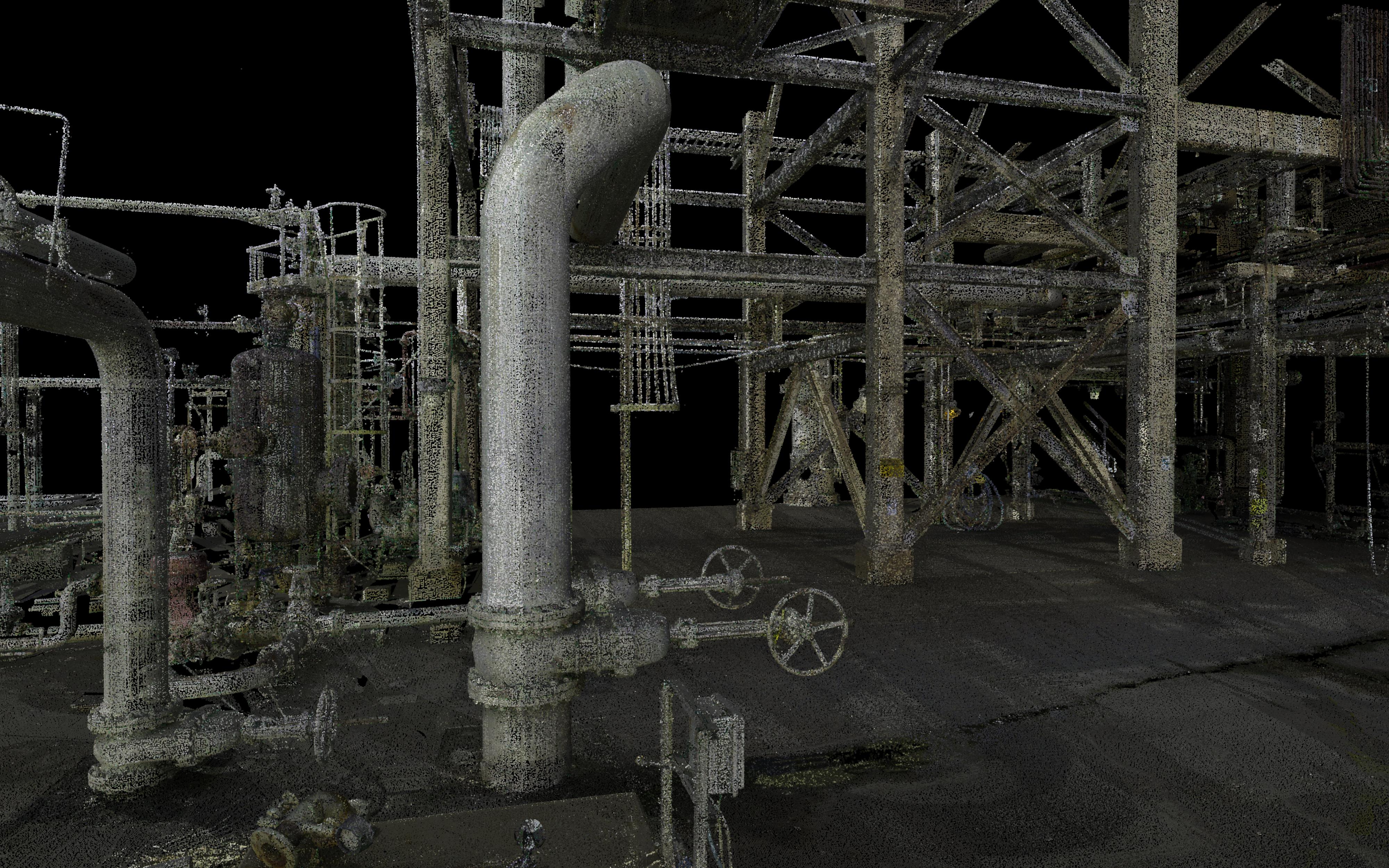
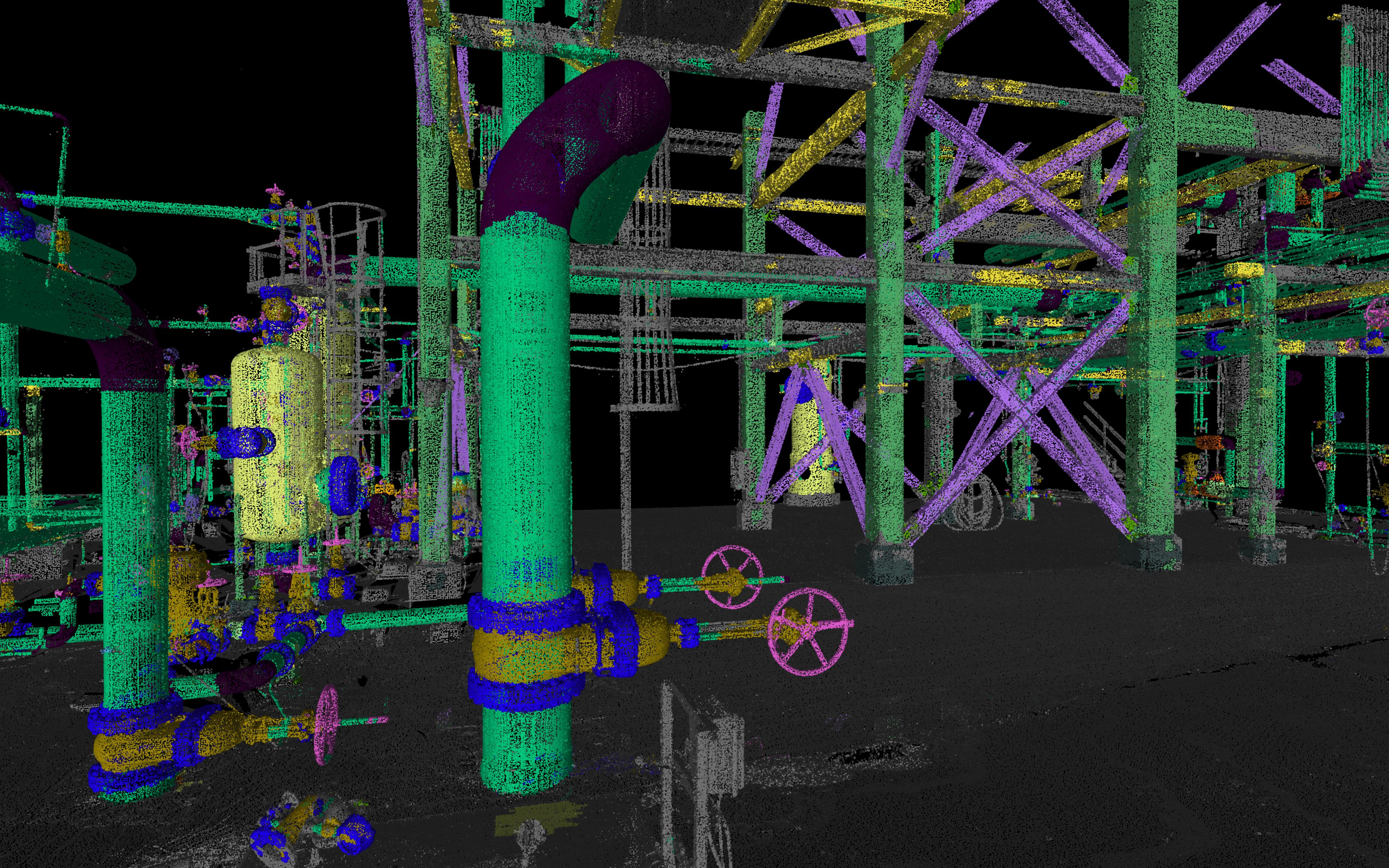
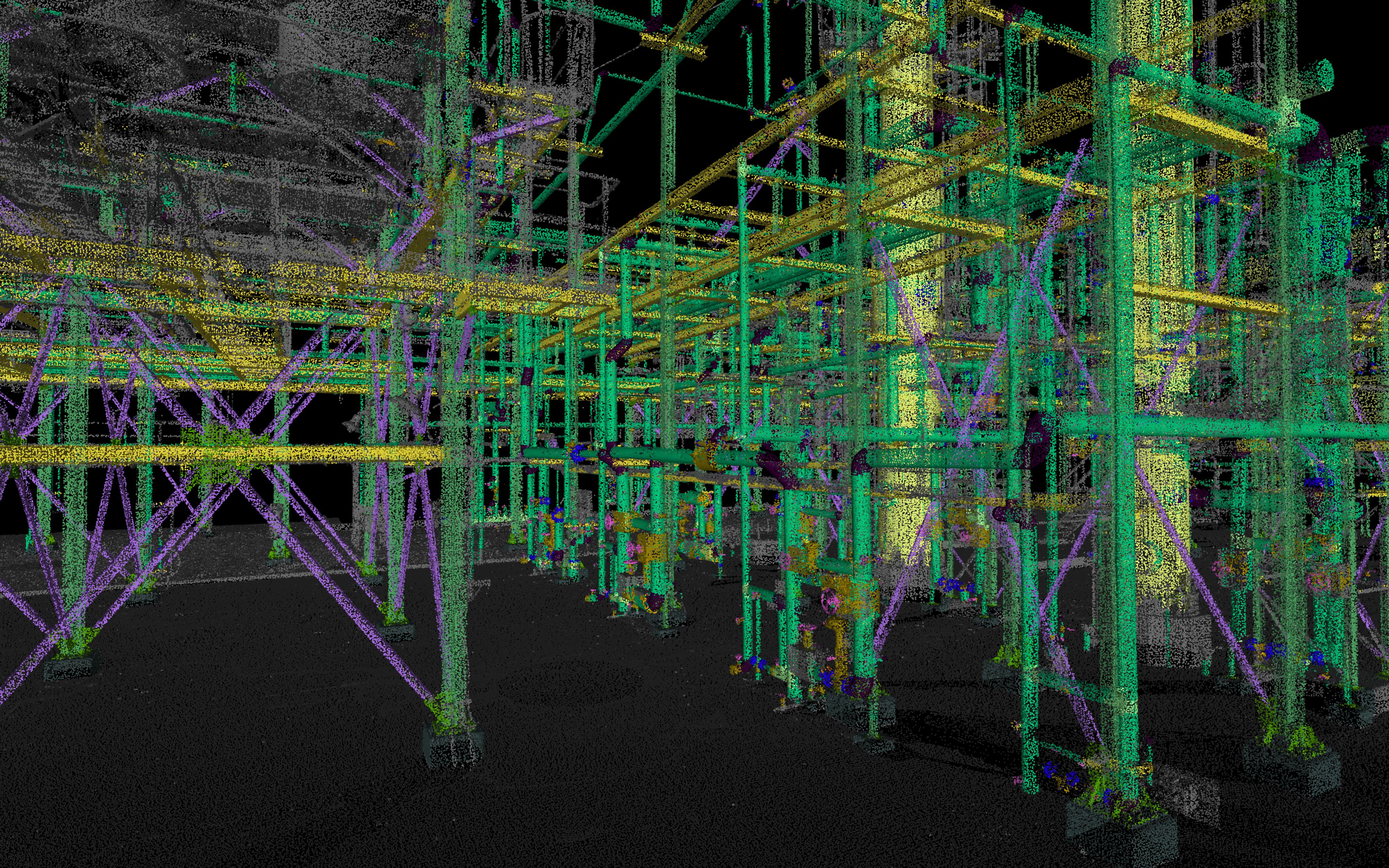
Plant
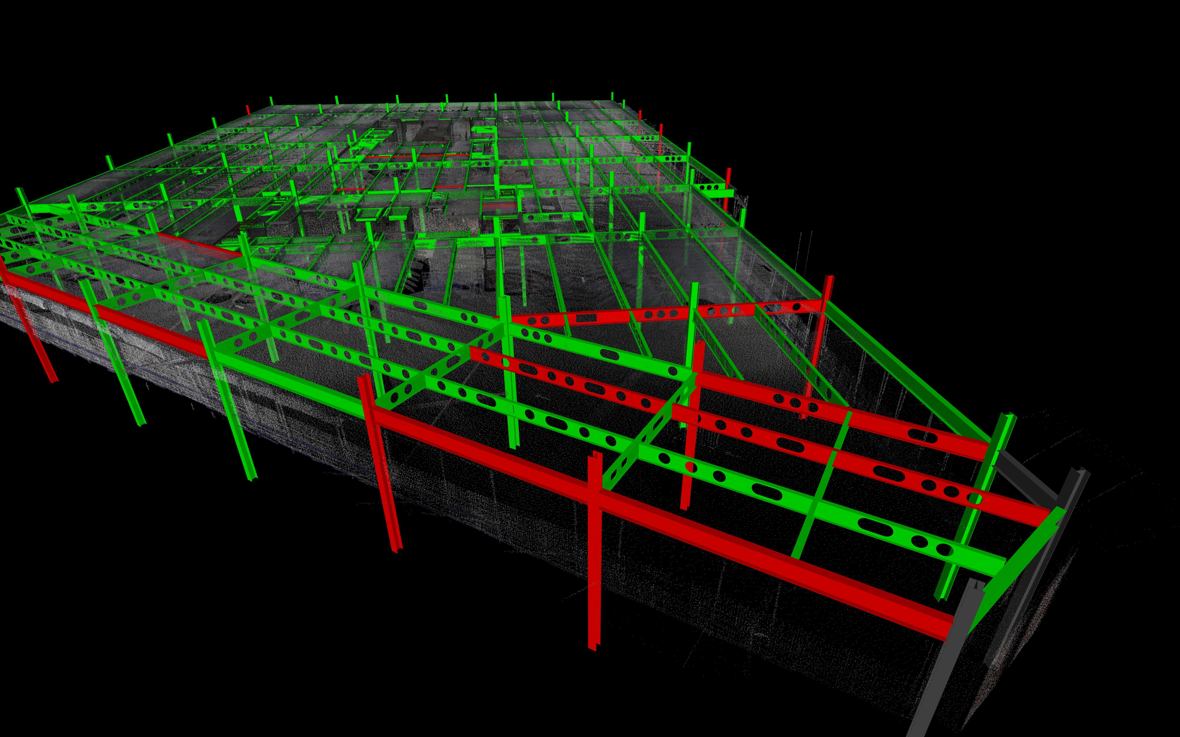
A new AI model is delivered for Plant Industry applications in Cyclone 3DR 2025.2. This version offers a significant improvement in comparison to the previous version and results in:
-
A better accuracy for existing classes such as reducers, elbows, valves and straight pipes.
-
New classes for piping assets such as pumps, valve wheels, flanges...
-
New classes for steel structures such as diagonals, columns, beams, connections or footings.
The Plant model improvement is massive and offers a gain of time to segment the data for any kind of Plant Facility workflows. Moreover, the combination of the auto-classification feature with Scan-to-Pipe offers an ideal way to model pipe systems from Cyclone 3DR 2025.2.
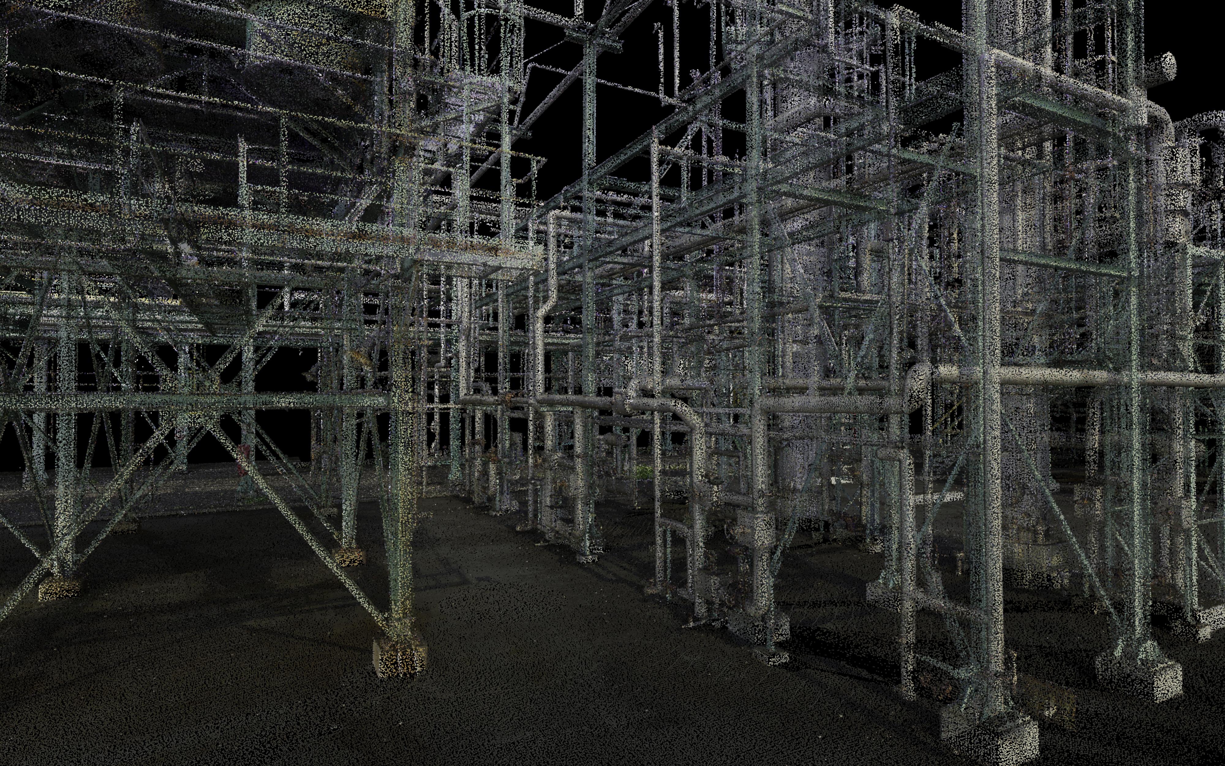
|
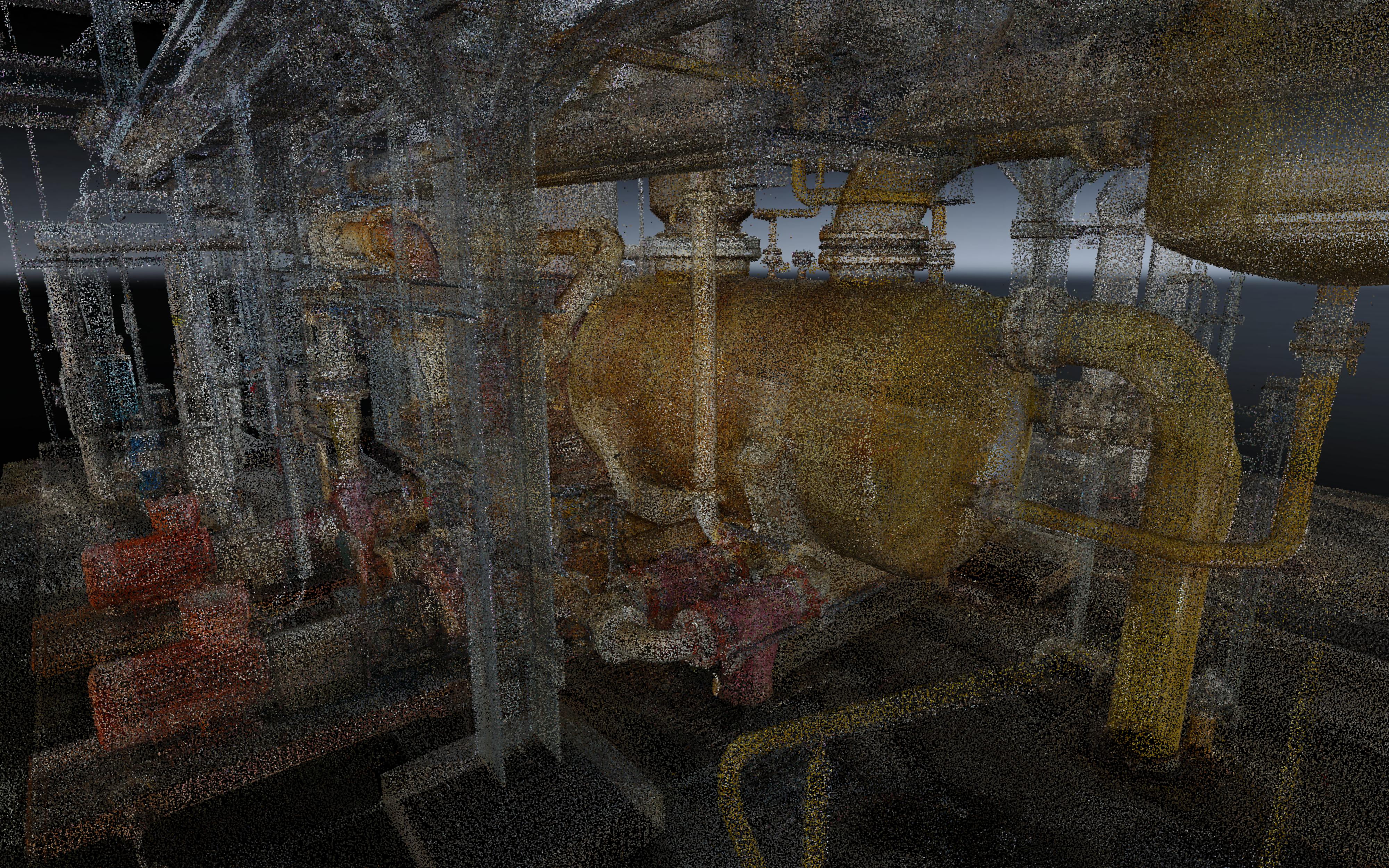
Point Clouds with RGB Representation |
Point Clouds with Classification [new Plant model] |
|---|---|
|
|
|
|
|
|
New “Edge & Corner” detection tools
New options in Point Selection toolbar
With Cyclone 3DR 2025.2, the Point Selection toolbar is completed with a new mode to detect relevant geometric points “Edge / Corner”. It is an easy way to pick points located in corners and on edges with high accuracy thanks to new back-end algorithms.
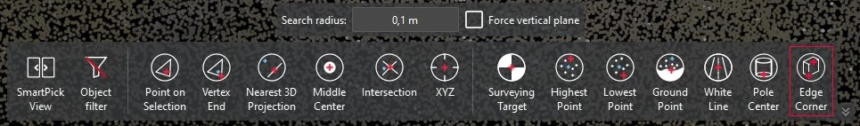
The new edge/corner option extends the powerful point selection toolset and allows for fast, accurate, and precise picks at edges and corners. The theoretical point eliminates the work of elaborate planar intersection workflows, repetitive slicing and guesswork in areas with sparse points.
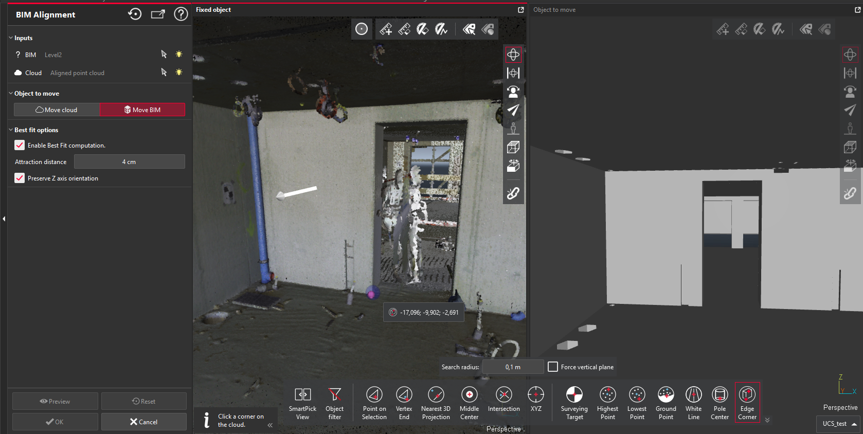
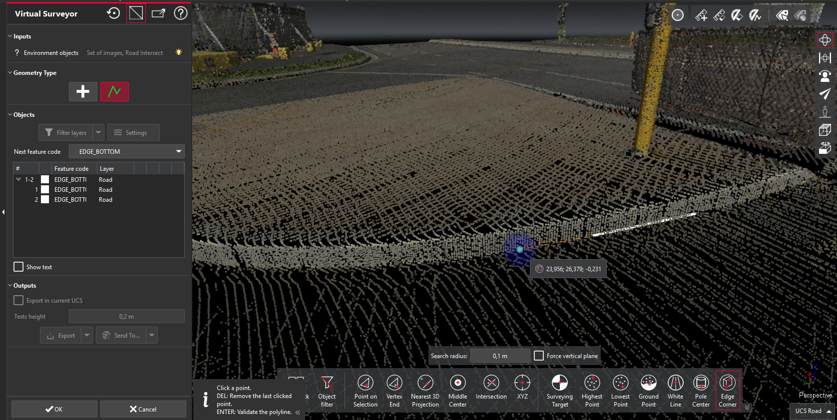
The edge/corner tool can be used for point creation, polyline drawing and more advanced features including but not limited to:
-
BIM Alignment feature: when clicking the temporary UCS on the point cloud
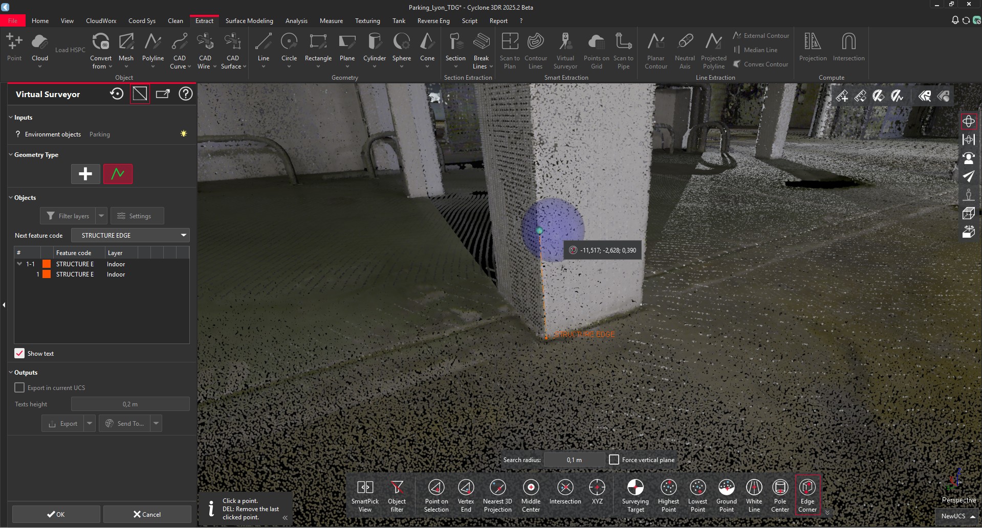
-
Virtual Surveyor: for border detection, interesting points to measure (Indoor or Outdoor), for structures, for facades, for road curbs …
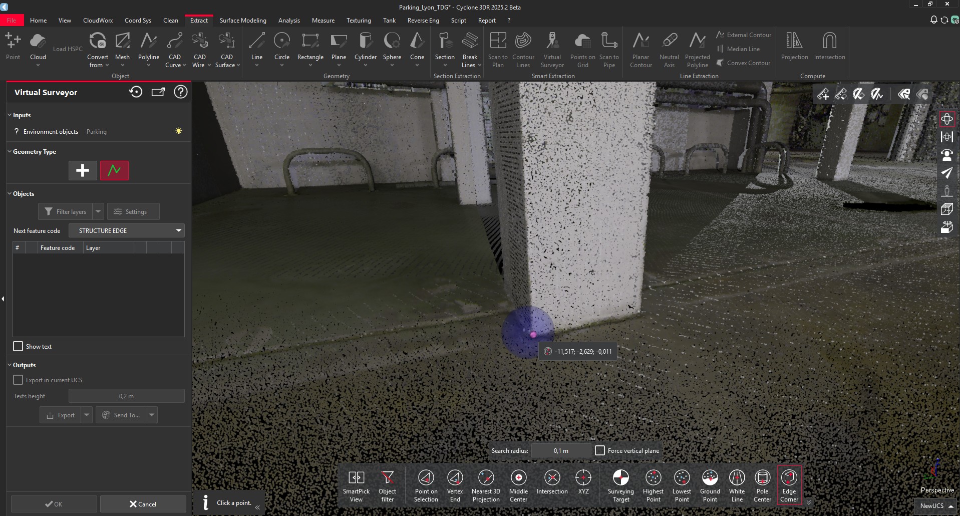
Once the point toolbar is active, the Edge / Corner button must be activated and the user can make the relevant clicks in the scene.
Two options are exposed:
-
The dimension of the search radius (similar mechanism to other point clicking tools)
-
A checkbox option to apply to force the verticality of one of the planes
For the best user experience, the feature automatically detects if the mouse cursor is closed to a corner or to an edge, based on the search radius dimension. That allows user to make multiple consecutive clicks with speed. To highlight the difference:
-
When the mouse cursor is close to a corner, the theoretical point is highlighted in light purple.
-
When it is close to an edge, the theoretical point is highlighted in light blue.
|
Corner detection |
Edge detection |
|---|---|
|
|
This feature is available to users with all the licenses.
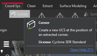
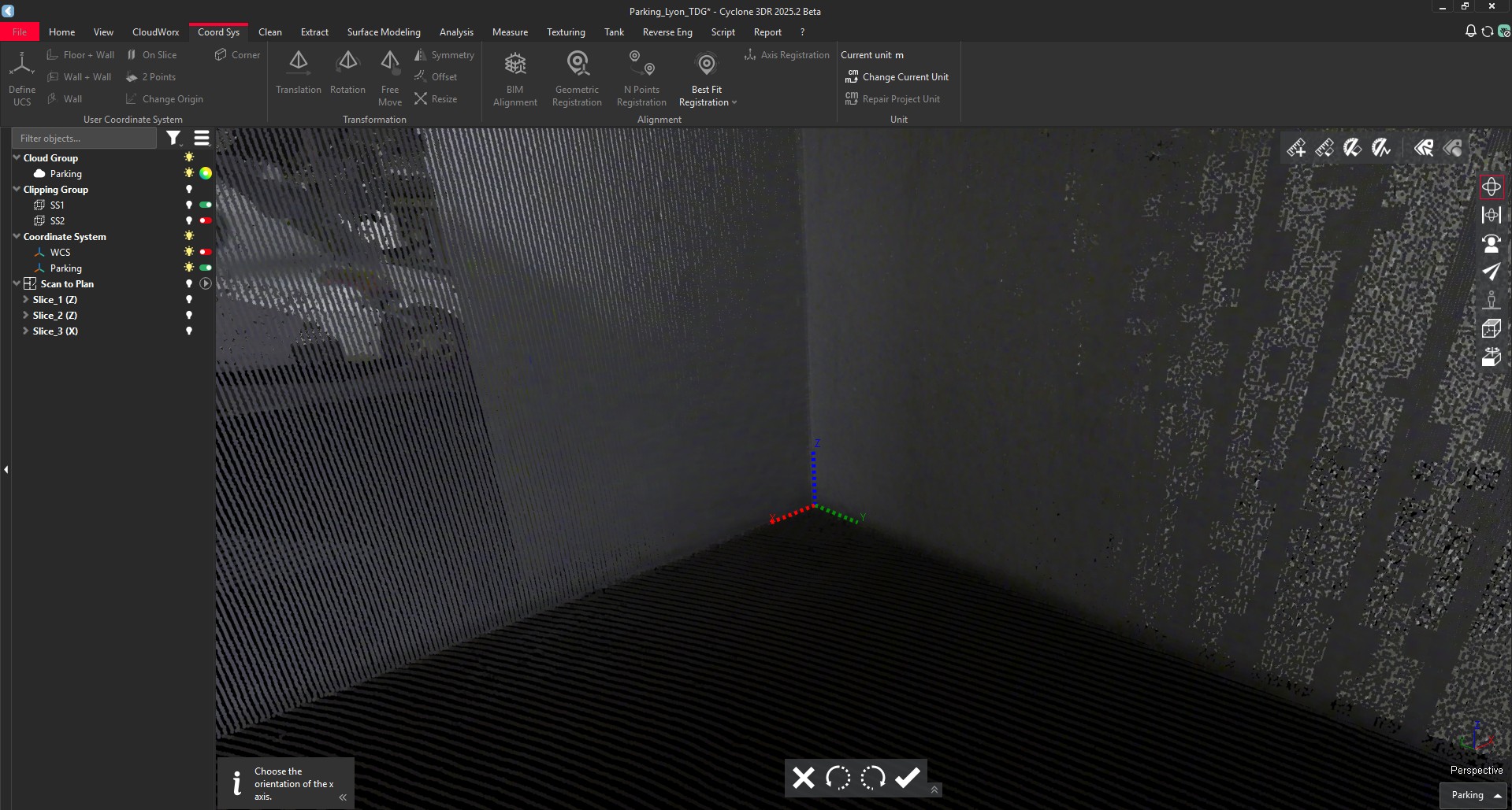
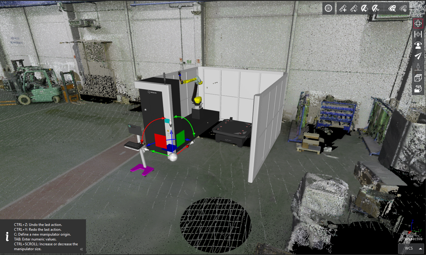
New UCS Corner
Based on the same 3D detection algorithm, Cyclone 3DR 2025.2 exposes a new 1-click way to create UCS from one corner.
The workflow is straightforward.
|
Actions |
Illustrations |
|---|---|
|
Start UCS Corner |
|
|
Make 1 click in a corner |
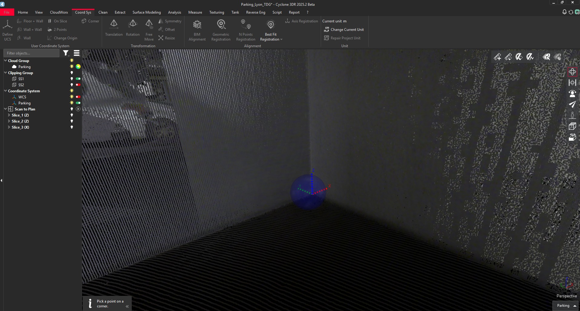
|
|
Adjust the orientation of the temporary UCS if necessary 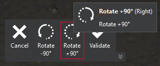
|

|
|
Validate the UCS 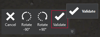
|
|
The new UCS is automatically created.
This feature is available to users with the Standard or PRO licenses.
LGSx improvements
As part of the continual improvement of the LGSx integration into Cyclone 3DR to facilitate the Leica Geosystems cross product experience, the LGSx workflow is improved with a better management of “Multi-sensor” LGSx projects, that combines both mobile and static sensor data.
LGSx project with the combination of static and mobile scanners offers a way to have a very extensive capture of the project, and can be useful for any kind of applications with Leica Geosystems solution.
The feature is compatible with LGSx generated with Cyclone REGISTER 360 PLUS 2025.0 and more recent versions.
Convert Project
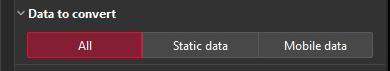
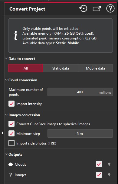
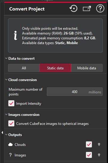
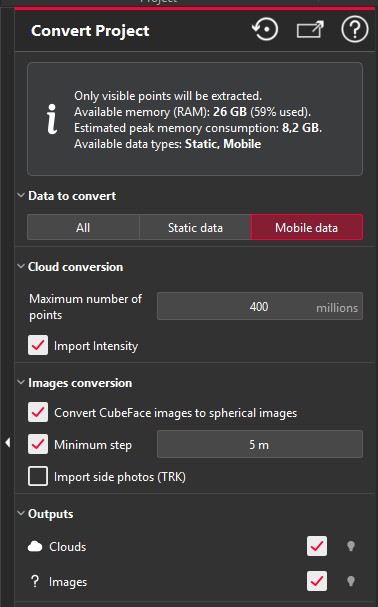
The mechanism is barely changed for LGSx workflows within Cyclone 3DR 2025.2. Once, the LGSx is imported in Cyclone 3DR, the user just has to go the CloudWorx menu and to execute Convert Project. The most significant change in the feature is the new toggle that suggests 3 modes: All | Static | Mobile.
|
All |
Static Data |
Mobile Data |
|---|---|---|
|
|
|
|
All the scans are converted into Cyclone 3DR. |
Only Static Data is converted. For example: RTC360, P-Series, BLK360 |
Only Mobile Data is converted. For example: TRK-Series, BLK2GO, BLKARC |
|
New conversion described below. |
No changes with previous version of Cyclone 3DR. |
No changes with previous version of Cyclone 3DR. |
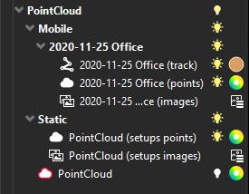
After the conversion of a Multi-sensor LGSx project, the Convert Project returns the point clouds in two different groups: Mobile and Static. This improvement offers more flexibility to Cyclone 3DR users, with an immediate way to segment the different types of scans. As an example, it is possible to apply a different cleaning/meshing strategy for a BLK2GO point cloud from an RTC360 job.
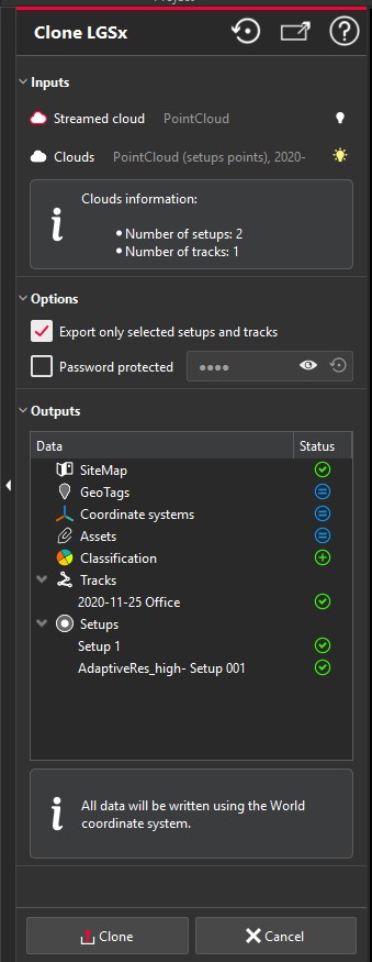
Clone LGSx
The Clone LGSx feature is compatible with Multi-sensor LGSx projects.
Once the converted point clouds are edited (cleaning, resampling, reduction, classification, etc.), they can be selected and processed with the Clone LGSx feature, as illustrated in the image below.
New tools in Cyclone 3DR Free Viewer
The Viewer application for Cyclone 3DR 2025.2 gets new unlocked features.
As a reminder, Cyclone 3DR Viewer:
-
is a free desktop application
-
can be executed without any licenses
-
does not offer a “save” or “save as” feature and addresses visualization only service.
Cyclone 3DR Viewer can be downloaded via myWorld or through the official website of Leica Geosystems.
New measure tools
The all new measurement experience that is deployed in Cyclone 3DR is also works as well in the Viewer. That includes :
-
An extended dedicated menu “Measure” to offer more tools to Cyclone 3DR Viewer
-
The new “Pick Info” feature
-
The renamed “Pick Analysis” feature:
-
In the Viewer, it is not possible to create new analysis (except Color Along Direction).
-
It is possible to measure any results from analysis or from geometry extractions created in the full Cyclone 3DR application.
-
-
The new “Edit Measures” feature, accessible directly from the menu or from the main settings.
-
The new visualization style:
-
Position in the scene
-
Adaptative info according to the color gradient
-
Customization of the measure contents
-
In addition, a series of measurement features are now unlocked in Cyclone 3DR Viewer:
-
Distance between a point and a plane
-
Distance between a point and a triangle
-
Distance between planes
-
Surface of a mesh or a polygon
-
Unit management feature
Free Move
With Cyclone 3DR 2025.2 Viewer, the Free Move feature is now available in the free Viewer application. The behavior of the feature is the same as the regular application and users should refer to the documentation center to learn the instructions.
The feature works with any type of 3D assets in the scene: point clouds, design models (BIM, CAD, COE, …), polylines, geometries, meshes, …
Thanks to the release of Free Move feature in Cyclone 3DR Viewer, two relevant applications are now possible in the viewer:
-
Visual and manual alignment of 2 different assets:
-
To facilitate overlay and alignment, change the transparency representation of object to contrasting colors.
-
A typical construction industry workflow is the visual alignment of a BIM Model with the point cloud. The Free Move is accurate enough and provides rotation and translation tools to manually position a BIM Model onto the point cloud. Free move makes it easy to visually inspect the differences between the as-built conditions and the engineering or architectural model.
-
-
Visual and manual alignment of one asset into its 3D environment:
-
To start, the user can import a design CAD model of a machine, an asset, a new component. Cyclone 3DR Viewer handles the same import formats as Cyclone 3DR regular application, such as DWG, DXF, COE, IFC, RVT, … It is also possible to use a mesh created in regular Cyclone 3DR.
-
Then, Free Move can be used on the imported CAD asset and positioned at the targeted location in the 3D environment.
-
A straightforward use case is asset management for Manufacturing, Plant Facilities, Construction environments, …
-
Another easy use case is clearance verification. Once the design model of the asset is positioned properly. Distance measurements can be made by the user.
-
Improvements
-
File > Export: The name of selected objects are now used as default filename.
-
File > Import LAS/LAZ: The support for UTF8 file name was added.
-
Rendering > Polylines: Better contrast of points with the “Segment + Vertices” representation.
-
Script functions updates:
-
SDialog.AddFileSelector allowing users to select files or directories was added.
-
Utility methods in SFile class to easily manipulate file paths and directories (ListEntries, GetDirectory, GetFileExtension , GetFileName) were added.
-
SFile.Open now creates intermediate directories if they don’t exist.
-
LocalizeValues methods (SPoly, SCloud) don’t output the SLabel object anymore.
-
Bug Fixes
-
Application: Projects could take a very long time to get saved with some objects like viewsets or set of polylines. Fixed.
-
File > Export ASCII: Accuracy errors were happening when exporting inspection values. Fixed.
-
File > Export LGSx: The latest class was missing while exporting classification information. Fixed.
-
File > Import COE: Data are now inserted into World Coordinate System. Fixed.
-
Scan to Pipe > Extract pipes: Due to unexpected resizing during pipes connections, the flange parameters are now locked after the extraction. It remains possible to unlock them. Fixed.
-
Script: The script engine was facing compatibility issue between the --silent argument and the OpenDoc function. Fixed.
Known Issues
-
The Documentation Center is only available in English.
-
Some DWG import and export issues might happen. It is recommended to use the Send to CAD feature.
-
If DXF can be imported with a standard version, DWG requires the AEC or PRO Edition. One workaround is to use the 3DR Send command from AutoCAD to Cyclone 3DR.
-
Export viewsets to PDF report or BCF tickets do not work with NVidia driver 573.48 version. Fixed with 580.92 version.
Deprecated Features
Leica Geosystems strives to provide support for the widest array of operating systems and file formats possible as is reasonable given current technologies and support from third-party partners.
With each release, we review our list of currently supported formats and operating systems in line with industry trends and announced product terminations.
Leica Geosystems may add or terminate support for a file format during any release. Obsolete operating systems will be supported for six months after their announced termination or the next major software release, whichever comes first. Server products will be supported in alignment with Leica’s Client License Manager (CLM) supported servers to guard users against incompatibility.
Cyclone 3DR 2025.2.0:
-
CloudWorx menu > Connect To: The connection to Cyclone Core has been removed.
-
Extract > Scan to Plan: FloorPlanner export is removed.
-
Label: Label object is deprecated with the introduction of the new Measure objects. However, labels from ancient projects are still supported in Cyclone 3DR 2025.2
-
Script functions:
-
SSurveying.FlattenCylindricCloud/Poly and SSurveying.UnrollAlong are now deprecated in favor of SSurveying.UnrollCloud/Mesh and SSurveying.UnfoldPolyline.
-
Operability with maintained Cyclone MODEL and SURVEY licenses
With the release of Cyclone 3DR 2025.2, the product can now be activated by Cyclone MODEL and SURVEY licenses as detailed below. This change allows users of those legacy products to operate Cyclone 3DR to become accustomed to the product and transition their workflows. Both Cyclone MODEL and SURVEY was phased out in September 2025.
All users with valid CCP or CCP which was valid as of for Cyclone SURVEY, can run this new version of Cyclone 3DR (Standard and Survey Edition features only).
All users with valid CCP or CCP which was valid as of for Cyclone MODEL, can run this new version of Cyclone 3DR (Pro Edition features).
Interoperability
Import / Export supported file formats
Please reference the Cyclone 3DR Technical Specification for a complete list of supported file types per license.
|
|
Import |
Export |
|
Point Cloud |
Files ASCII (*.asc, *.csv, *.xyz, *.yxz…) Leica Geosystems (*.pts, *.ptx) and LGS/LGSX (*.LGS/LGSx) Leica Nova MS50/60 (*.sdb, *.xml) ShapeGrabber (*.3pi) 3DReshaper binary file (*.nsd) AutoDesk DXF (*.dxf) STL (*.stl) Polyworks (*.psl) Leica T-Scan + Steinbichler (*.ac) LIDAR data (*.las; laz) Other ASCII (*.*) Zoller and Fröhlich *(.zfs - *.zfc) PLY points without triangles (*.ply) ESRI ASCII (raster format *.asc) FARO (*.fls - *.fws) POLYWORKS (*.psl) E57 (*.E57 files) LandXML files (*.xml) Riegl (*.RDBX) |
ASCII FILES (*.asc, *.csv…) Binary files (*.nsd) Leica Geosystems (*.pts, *.ptx, *LGSx) E57 (*.e57) IGES (*.igs) LAS (*.las) LAZ (*.laz) Autodesk DXF (*.dxf)
|
|
Mesh |
STL format (*.stl) Binary PBI format (*.pbi) DXF 3Dface format (*.dxf) Ascii POLY format (*.poly) OBJ format (*.obj) Ascii Leica format (*.msh) OFF files (*.off) PLY (*.ply) GLB format (*.glb, *gltf)
|
Ascii and binary STL format (*.stl) Binary PBI format (*.pbi) DXF 3Dface format (*.dxf) Ascii POLY format (*.poly) Vertices only (*.asc) DXF polyline (*.dxf) Ascii Leica format (*.msh) PLY (*.ply) LandXML (*.xml) OBJ format (*.obj) GLB format (*.glb) FBX format (*.fbx) IFC / IFCSite type (*.ifc, *.ifczip) |
|
Contour / Section |
IGES format DXF polyline format Binary MLI format (*.mli) Alignment (*.landXML)
|
IGES format DXF polyline format Binary MLI format (*.mli) ASCII formats |
|
CAD / BIM Models |
IGES STEP DWG IFC RVT COE |
IGES STEP DXF IFC (Piping models) COE (Piping models) |
|
Project |
Cyclone 3DR (*.3dr) DXF - DWG XML Cyclone ModelSpace View (from IMP) |
Cyclone 3DR (*.3dr) DXF PDF 3D SKETCHFAB |
|
Report |
|
CSV BCF |
|
Image |
BMP JPEG JPG PNG |
Ortho-image including georeferencing information as TXT file JPG JPEG BMP PNG TIF (Ortho-image only) |
|
Trajectory (mobile scanner) |
Leica Geosystems (*LGSx) |
Leica Geosystems (*LGSx) |
Compatibility with native JetStream point clouds
Features with LGSx
The following commands can use native JetStream point clouds (LGS/LGSx files, Cyclone REGISTER 360 PLUS, Cyclone ENTERPRISE) as inputs. In other words, it is not required to proceed a CloudWorx > Convert project step prior to execution of the listed features.
|
Menu |
Feature |
Comment |
|
Extract |
Virtual Surveyor |
No selection is required for this feature. Thus, it can be used for any kind of object in a 3DR project. |
|
Extract |
Scan to Plan |
|
|
Surface Modeling |
Scan to Mesh |
A clipping box as input is recommended to define an area of interest. |
|
Analysis |
Stockpile |
|
|
Analysis |
FF/FL Analysis |
A maximum number of points is exposed in the first step of the workflow. It is recommended to keep a high value to execute an accurate analysis on a dense point cloud. |
|
Analysis |
Visual Notes |
No selection is required for this feature. Thus, it can be used for any kind of object in a 3DR project. |
The functionalities of the menus View, CloudWorx and Script can be used for JetStream point clouds.
Images from LGSx
With the capacity to stream images from LGSx files since the 2025.1.0 version of Cyclone 3DR, it is not required to convert the project to visualize the camera images anymore. However, it remains necessary to convert them when the images are used for specific features:
|
Menu |
Feature |
Comment |
|
Texture |
Smart Texture Standard Texture Edit Mask |
It is mandatory to convert the images from the LGSx when a texturing workflow with images is expected by the user. |
|
Image object usage |
Group / Ungroup |
In the treeview, only the converted images from the LGSx file can be grouped and ungrouped. |
Point Selection with LGSx
The standard point selection tools are enabled by the Standard license.
|
Standard tools |
Point on Selection |
Vertex End |
Nearest |
Middle Center |
XYZ |
|
3DR Native |
|
|
|
|
|
|
LGSx |
|
|
|
|
|
|
Advanced tools |
Target |
Highest |
Lowest |
Ground |
White Line |
Pole Center |
Edge Corner |
|
Licences |
Survey, AEC, Plant |
Survey, AEC, Plant |
Survey, AEC, Plant |
Survey |
Survey |
Survey |
Standard |
|
3DR Native |
|
|
|
|
|
|
|
|
LGSx |
|
|
|
|
|
|
|
Connect to Cyclone FIELD 360
The connection from Cyclone FIELD360 to Cyclone 3DR (2024.0 and later versions) projects is limited to TLS sensors:
-
P-Series
-
RTC360
-
BLK360, BLK360 G1
Generic specifications
Leica Cyclone 3DR 2025.2 compatibility
-
Cyclone 3DR is compatible with CLM 2.26.0 and higher.
-
Cyclone 3DR is compatible with LGS/LGSx files.
-
Cyclone 3DR is compatible with Cyclone ENTERPRISE 2022.0 and higher.
-
Cyclone 3DR is compatible with Cyclone REGISTER 360 2025.0 and higher.
Computer specifications
|
Computer specifications |
Minimum |
Recommended Including for Automatic Classification |
Recommended for Cyclone 3DR Touch Mode |
|---|---|---|---|
|
CPU |
2 GHz Dual Quad Core i7 or higher (i5 minimum) |
3.5 GHz Intel® Core™ i7 or higher |
Microsoft Surface PRO Core i7 1.5 GHz |
|
RAM for 64-bit OS |
32 Gb RAM |
64-256 Gb RAM |
16 Gb RAM |
|
Graphics Card |
NVidia Quadro or GeForce 1 GB
|
NVidia with GPU capabilities
|
|
|
Operating system |
Microsoft Windows 10 (Build 1809), 11 (64 bits supported) |
||
|
Hard Disk free space |
3 Gb |
20 Gb |
3 Gb |
|
Other |
|
CUDA® 12.8 Toolkit (from NVidia). The 12.8 version of CUDA is mandatory for Auto-Classification. |
|
Installation and Licensing Recommendations
Installation update procedure
-
Launch the Cyclone 3DR EXE and follow the instructions in the Setup Wizard
-
Select the option to update Cyclone 3DR (or repair if you want to change installing options)
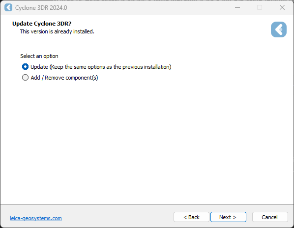
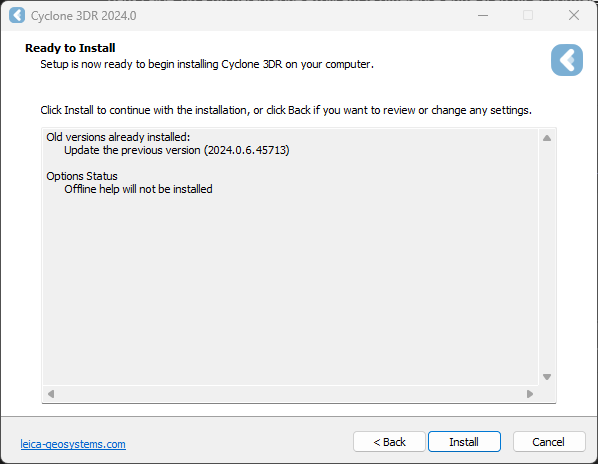
-
Complete the installation by selecting “Install”.
Licensing setup
-
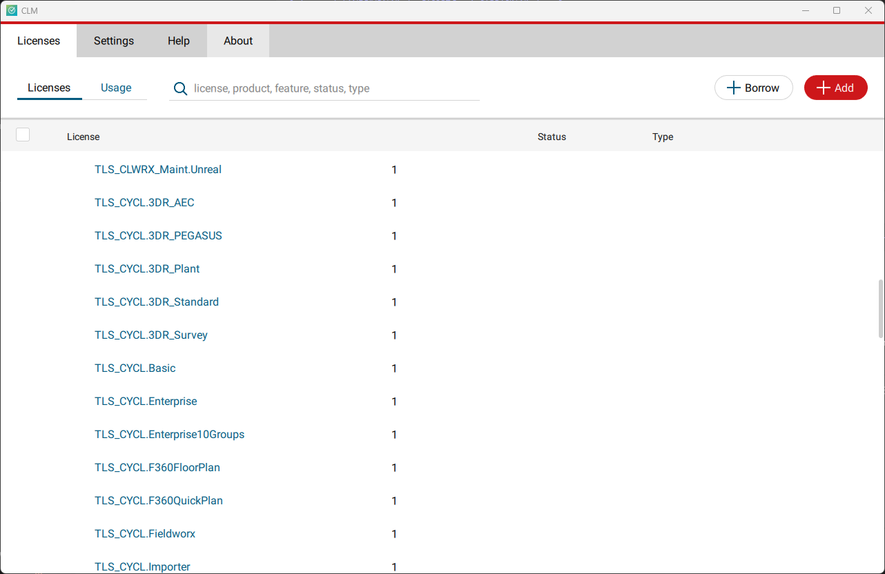
Once you have installed Cyclone 3DR, open the Client License Manager for Floating Licenses via Cyclone 3DR (Home/Settings/License) or via the program located here:
Start Menu | All Programs | Leica Geosystems | Client License Manager
Be sure to choose the CLM Floating option (there are two CLM options and the Nodelocked CLM will not activate your license).
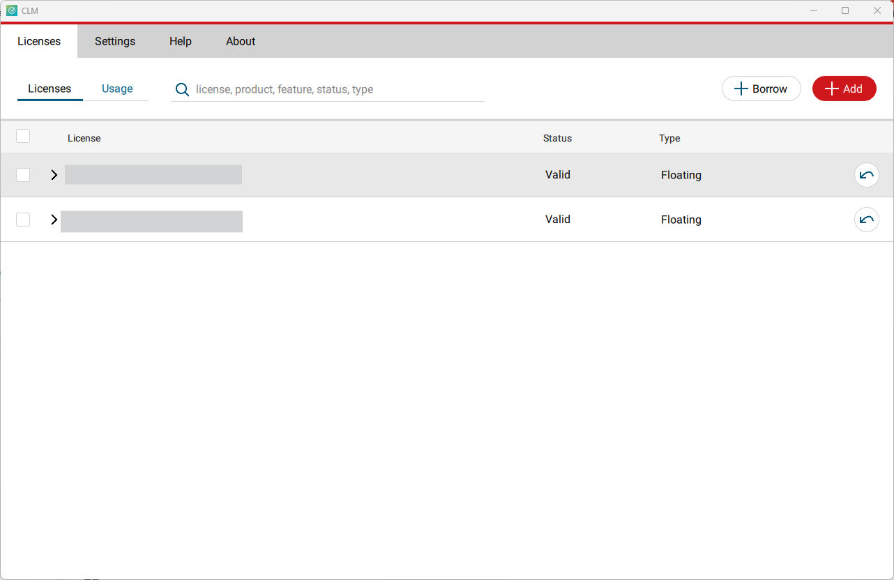
-
Click Add.
-
Enter your Entitlement ID (EID) in the field (copy / paste). To enter multiple EIDs separate them with a semicolon ";" and no space.
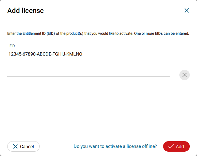
-
After you have entered your EID, click on the Add button in the bottom right of the page.
-
Once your licenses are activated you can close CLM and launch or return to Cyclone 3DR.
-
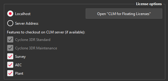
Go to Home | Settings and select License.
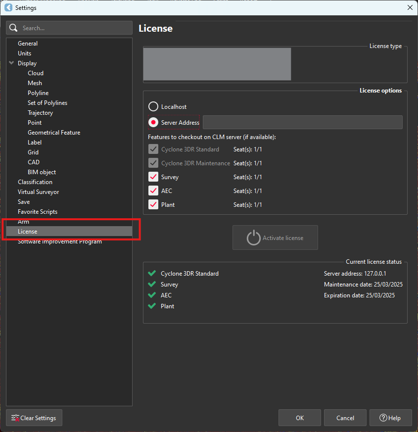
-
If you have entered the EID inside your local CLM, select Localhost. If the license is on a dedicated server, enter the server’s name in Server Address.
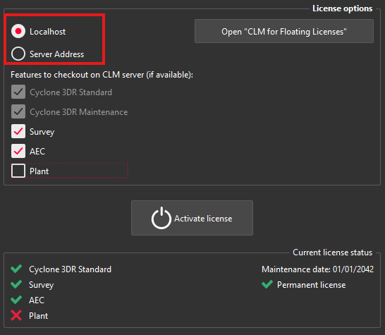
-
You can select the features you want to check out from CLM. The available options to checkout will correspond to the options you purchased which are contained in your EID.
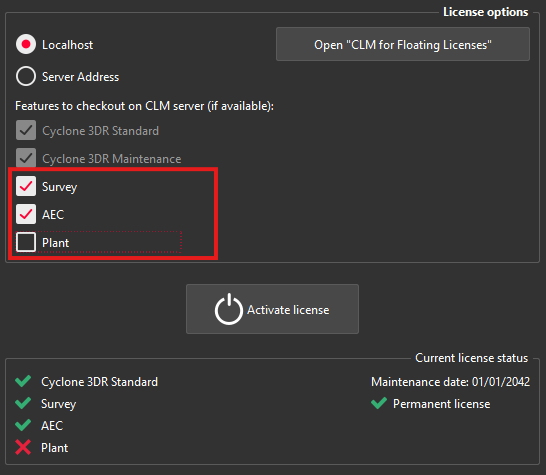
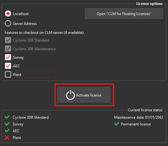
-
Once the options are selected, click on Activate license.
Licensing
All users with valid CCP or CCP which was valid as of for Cyclone 3DR, can run this new version of Cyclone 3DR.
All users with valid CCP or CCP which was valid as of for 3DReshaper, can run this new version of Cyclone 3DR with no new license required. Users with 3DReshaper licenses with expired CCP must migrate to Cyclone 3DR in order to continue to access updates and support. Please contact your sales or support personnel for more information.
All users with valid CCP or CCP which was valid as of for Cyclone SURVEY, can run this new version of Cyclone 3DR (Standard and Survey Edition features only).
All users with valid CCP or CCP which was valid as of for Cyclone MODEL, can run this new version of Cyclone 3DR (Standard and Plant Edition features only).