2024.1 | Cyclone 3DR Release Notes


Cyclone 3DR 2024.1.0
What’s New
Cyclone 3DR 2024.1.0 is a major release that includes new features and improvements to the product, for both the Desktop and Touch Mode interfaces.
The main changes and new functions are summarized here:
Floor Flatness / Floor Levelness analysis, a new workflow that enables an ASTM-E1155 compliant analysis [AEC Edition]
Next features within Scan to Pipe [Plant Edition]
New asset: Y and T branches
Auto-fitting capacity of reducers and elbows
Duplicate pipe traces with a free move tool
New export features including table of pipe information to CSV
User Interface improvements (Undo/Redo, Hotkeys, …)
Statistics, a new analysis tool to extract detailed table and graph from any kind of analysed object [Standard Edition]
Point Cloud Classification [Survey, AEC or Plant Editions]
New version of classification engine providing faster performance: 20% faster than Cyclone 3DR 2024.0
New Plant classification model dedicated to piping networks
LGSx integration updates [Standard Edition]
New point cloud attribute features [Standard Edition]
Separate by Attributes
Support of multi-return values
LAS/LAZ format import updates
Connect to Reality Cloud Studio updates
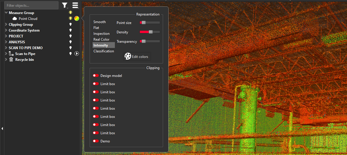
Improvements for Inspection and Intensity attributes
Scanning directions
Operability with maintained Cyclone MODEL and SURVEY licenses
With the release of Cyclone 3DR 2024.1, the product can now be activated by Cyclone MODEL and SURVEY licenses as detailed below. This change allows users of those legacy products to operate Cyclone 3DR to become accustomed to the product and transition their workflows. Both Cyclone MODEL and SURVEY will be fully phased out in 2025.
All users with valid CCP or CCP which was valid as of 6 July 2024 for Cyclone SURVEY, can run this new version of Cyclone 3DR (Standard and Survey Edition features only).
All users with valid CCP or CCP which was valid as of 6 July 2024 for Cyclone MODEL, can run this new version of Cyclone 3DR (Standard and Plant Edition features only).
Floor Flatness / Floor Levelness [ASTM E1155 Standard]
Cyclone 3DR now includes a Floor Flatness/Floor Levelness routine which adheres to ASTM 1155 standards. This highly demanded feature for the construction market, ensures that users can easily create their full suite of deliverables in Cyclone 3DR rather that requiring additional tools or products to produce discrete analysis.
A wizard-guided workflow supports users through their analysis.
The basic workflow is as follows. It is detailed with full instructions below.
Select a point cloud.
Note that JetStream point clouds like LGSx or those streamed from Cyclone ENTERPRISE or Cyclone REGISTER 360 PLUS do not need to be converted.
Execute FF/FL Analysis from the Analysis menu.
Execute the 5 steps of the guided process (detailed below).
Open the report editor to export a PDF document.
This feature is available to users with the AEC or PRO licenses.
FF-FL workflow
The guided workflow is composed of 5 steps:
Extract floor
Define test surface
Define test section(s)
Define sample lines
Adjust sample lines
Like all wizard-guided workflows in Cyclone 3DR, it is possible to go backward or forward in the process via the Previous/Next buttons or via the workflow ribbon.
The workflow is defined by ASTM E1155 Standard only in Cyclone 3DR 2024.1.
Extract floor
This step helps the user define a clean area of data with a limit box and quickly detect the floor in a single click. This floor extraction step allows the user to conduct FF/FL analysis without any previous cleaning operations.
Any active limit box, aligned with active UCS and activated prior to starting the workflow will be used rather than prompting the user to create the limit box again.
Define a tolerance extraction of the floor (noisy points will be removed from this first step).
Instructions for each step of the workflow will appear in the lower left of the viewing panel. Follow the instructions.
Click on the floor.
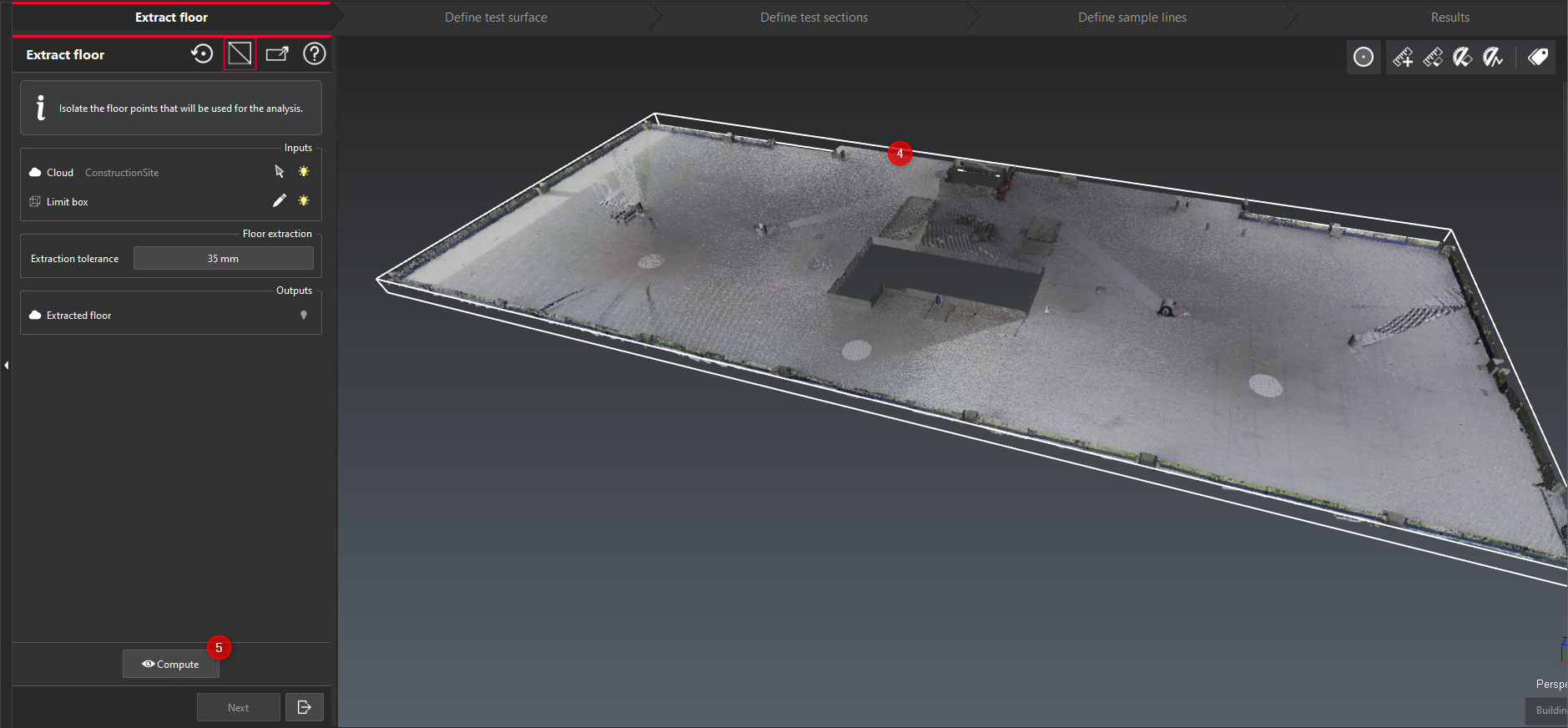
After the click on the floor, a smart limit box is created to clip relevant floor points and exclude the rest of the scene.
Click Compute to enable the floor detection and to keep only the relevant points for the analysis.
Note for LGSx and JetStream point clouds:
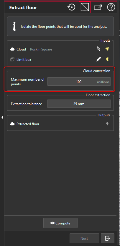
The conversion of a JetStream point cloud is not required before starting the execution of FF/FL Analysis.
An additional parameter is exposed to define the maximum number of points inside the smart limit box that is created by the 1-click floor extraction. It is recommended to use a significant number of points to ensure an accurate FF/FL result.
Define test surface
This step allows the user to create a Test Surface, defined according to the ASTM E1155 Standard. The minimum size of the Test Surface is defined by the ASTM E1155 Standard.
The test surface must meet minimum length, width and area requirements.
The test surface defines the area of the colormap.
The test surface can contain multiple Test Sections (following step). By including multiple test sections in a single test surface, a single floor analysis report for slabs with multiple sections will be created.
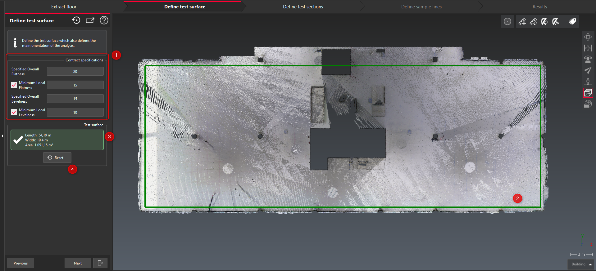
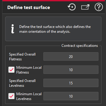
Define the FF/FL contract specifications. The minimum local values are optional. The user can use to calculate mimimum values when they are required by the contract specifications (ASTM E1155 requirements).
Click Add and define the rectangle representing the Test Surface by clicking 3 points on the extracted floor.
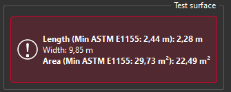
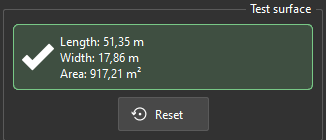
Since the size the Test Surface relies on the ASTM Standard requirement, a notifier is exposed to the user to check the minimum dimensions of the surface (length, width and area).
The notifier on the image above is in green with a check market in the dialog box. It means that the sections are ASTM-compliant. When the requirements are not fulfilled, the notifier is red.
The test surface cannot be created if the dimension requirements are not fulfilled to ASTM 1155 standards.
The dimensiosn requirements can not be edited. They are defined by the ASTM 1155 Standards.
Click on Reset to remove the in-progress test surface and start over.
Click on the space key during test surface creation to switch from a 3-click creation mode to a 2-click creation mode. Create a UCS prior to beginning the workflow to use this option.
Notifier when the dimensions of the Test Surface are not ASTM compliant | Notifier when the dimensions of the Test Surface fits ASTM requirements |
|---|---|
 |  |
Define test section(s)
Once a test surface is defined, the user moves on to the creation of the test section(s). Users can create multiple test sections according to ASTM standard, with the following requirements for the test sections:
They must remain inside the test surface.
They must have minimum dimensions to remain compliant.
They remain aligned according to the test surface (the parallelism of the sections is forced).
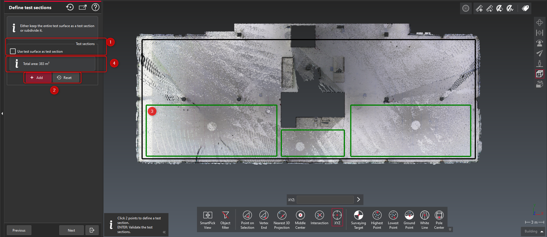
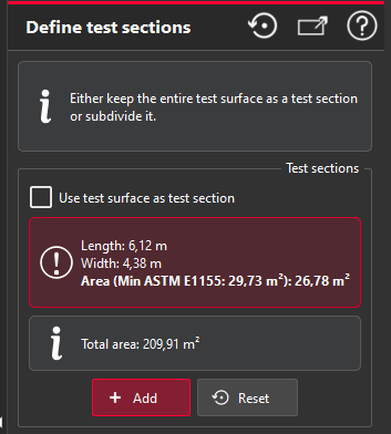
Choose whether to create multiple test sections. Check the Use test surface as test section box to execute the analysis on the full surface.
If the option is not checked, then it is possible to add multiple Test Sections. Click Add to begin adding sections to the surface.
Use a 2-click method to create the test sections within the test surface.
A test section cannot be created if the dimension requirements are not met.
A test section cannot be created if any pick falls outside of the test surface.
The total area of the analysis will be displayed to help the user stay compliant with ASTM standards.
Define sample lines
Once a test section is defined, the use will create ASTM-compliant sample lines.
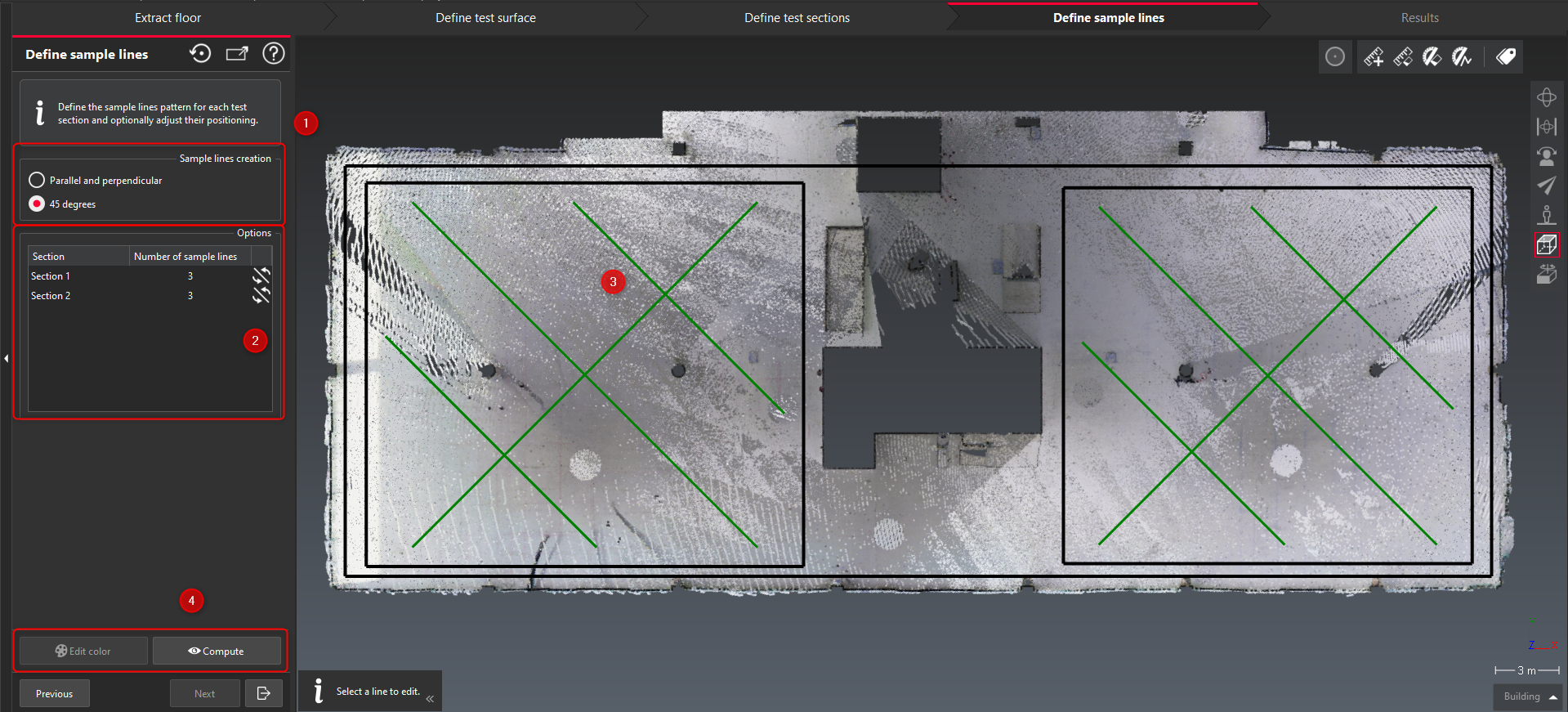
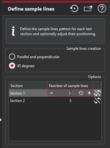
Define which method to create the sample line architecture
Parallel and perpendicular (requirements from ASTM Standard)
45 Degree (or fishbone-like). The 45 Degree orientation is a requirement from the ASTM Standard
In the options, it is possible:
To change the number of sample lines (for each Test Section). To remain compliant with the ASTM Standard, it might be necessary to add more lines (in that case a warning is exposed to the user).
To reverse the orientation of the main line of the 45 Degree method.
When the lines intersect known obstacles (worksite equipment or holes for example), it is possible to click on a line and adjust its position to avoid these obstacles. (see below)
Note that ASTM Standard requires a uniform distribution of the sample lines.
Click on Compute to create the colormap and calculate the FF/FL values of each sample line.
users can edit the colors of the colormap in a later action.

Adjust the positions of the sample lines:
In the example below, it is obvious that some lines are crossing holes or are located in areas of sparse points. When this happens it will be automatically detected and the issues and highlighted in red.
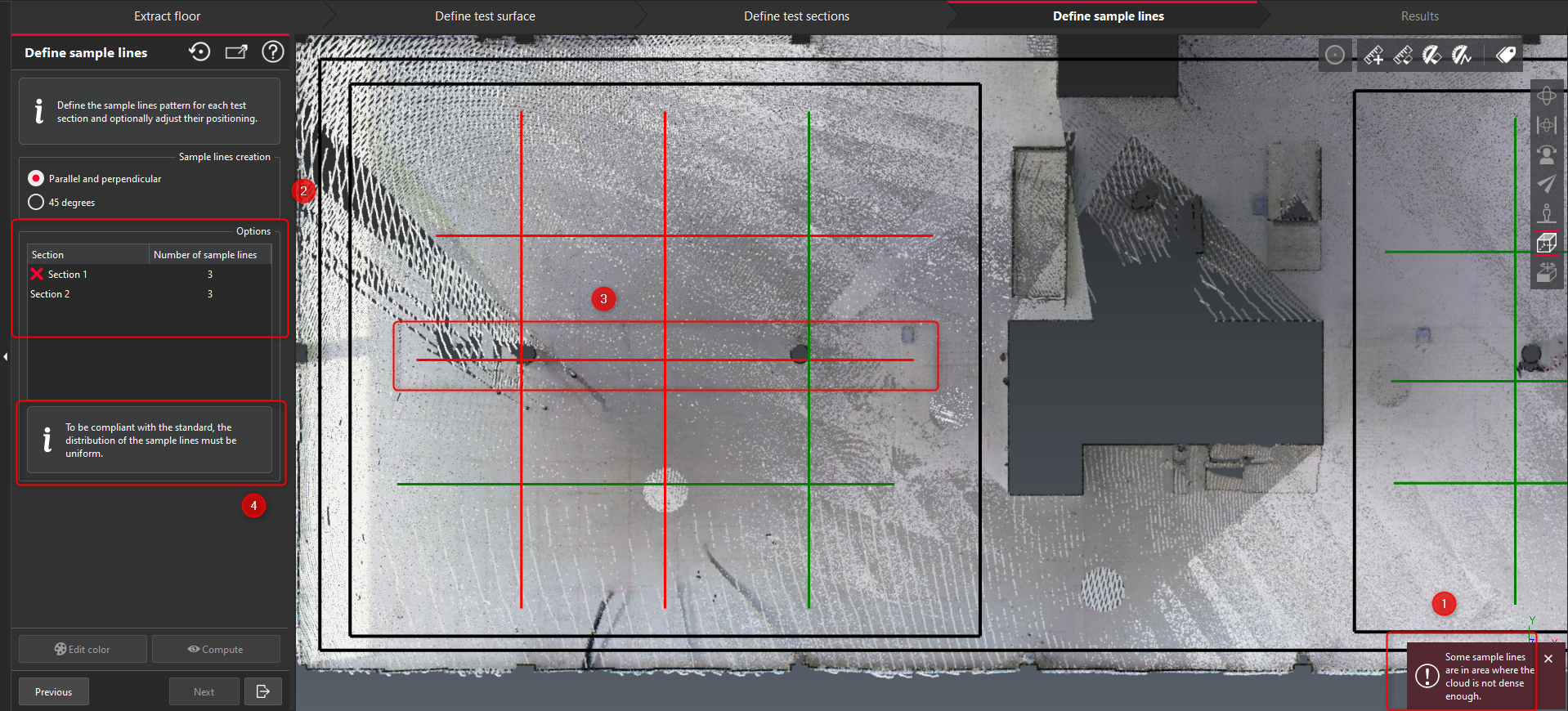
Error message to notify the user.
In the list, the sections which need attention are indicated by a red X.
Click on each red line to adjust its position and avoid the obstacles. All red lines and errors must be resolved to conduct the FF/FL analysis.
The requirement for uniform distribution of the sample lines is displayed to the user.
Results
Once the sample lines are created and compliant, verify the results from the analysis and adjust the generated labels.
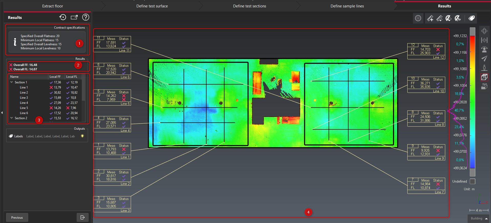
The contract specifications defined by the user are presented to ensure the user can easily reference them while reviewing the results.
Results of overall values: Overall FF and Overall FL.
A green “Check” marker means the value passes.
A red “Cross” marker means the value fails.
Results of local values: Local FF and Local FL values are exposed, and the FAIL/PASS markers are visible only if the user defined minimum values for verification during the test surface definition step. Click on each line of the table to identify the referenced sample line.
The scene represents the lines and the labels containing the FF/FL values.


FF-FL report
Once the analysis completed, a report chapter is automatically created. The report can be delivered as either a PDF or CSV report.

The PDF report contains the following default sections:
A summary page (image above) of the full analysis, defined by the test surface with:
the complete colormap
the contract specifications
the FF/FL values and the PASS or FAIL conclusion
A page for each test section
a single test section page will be included if the user selected Use test surface as test section.
A page for each sample line

ASTM Compliance
With Cyclone 3DR 2024.1, the FF/FL feature is compliant with the E1155 ASTM Standard. That means that:
All the verifications and calculations are done according to this specific standard that is defined.
Appropriate test surface and test section parameters are enforced.
Sample lines can only be created in compliant orientations.
All results are presented with imperial units.
The “Metric version of ASTM” for FF/FL verification is not supported.
It is possible to execute the workflow when the Cyclone 3DR project units is metric. However, the FF/FL verification will be done with imperial values regardless of the project units. As a reminder, FF/FL values are unit-less. It is specified in the final report that E1155 ASTM Standard is used for the verification.
Scan to Pipe updates
With Cyclone 3DR 2024.1, the scan to pipe workflow has been further improved as described below. These additional features help to improve the efficiency and effectiveness of the scan to pipe workflow allowing users to quickly achieve high quality results.
New asset: Y and T branches
New auto-fitting capacity of reducers and elbows
New time-saving tools
Duplicate pipe traces with a free move tool
User Interface improvements (Undo/Redo, Hotkeys, …)
New export options including table of pipe information to CSV
This feature is available to users with the Plant or PRO licenses.
New asset: T and Y branches
In addition to the already supported straight segments, bend elbows and reducers, the scan to pipe workflow now supports T and Y branches. A new action is exposed to the users to select the appropriate branch option.

To connect two traces or pipe runs with a T or Y branch, the user will:
First, prepare the 2 traces that will be connected with a branch. T and Y branches are not placed automatically.
Second, verify the diameter of the traces: note that a secondary trace that connect in the middle of a main trace must have a lower diameter than the main trace (in the area of the connection). It is possible to edit the diameter in the pipe geometric information from the dialog box.
Third, execute the branch connection through either of the two workflows below based on the configuration of the two traces being joined.
Adding a branch in the middle of a trace
Always select the “reference” straight pipe from the main trace first.
Note that in Scan to Pipe, the first selected object is always the reference.
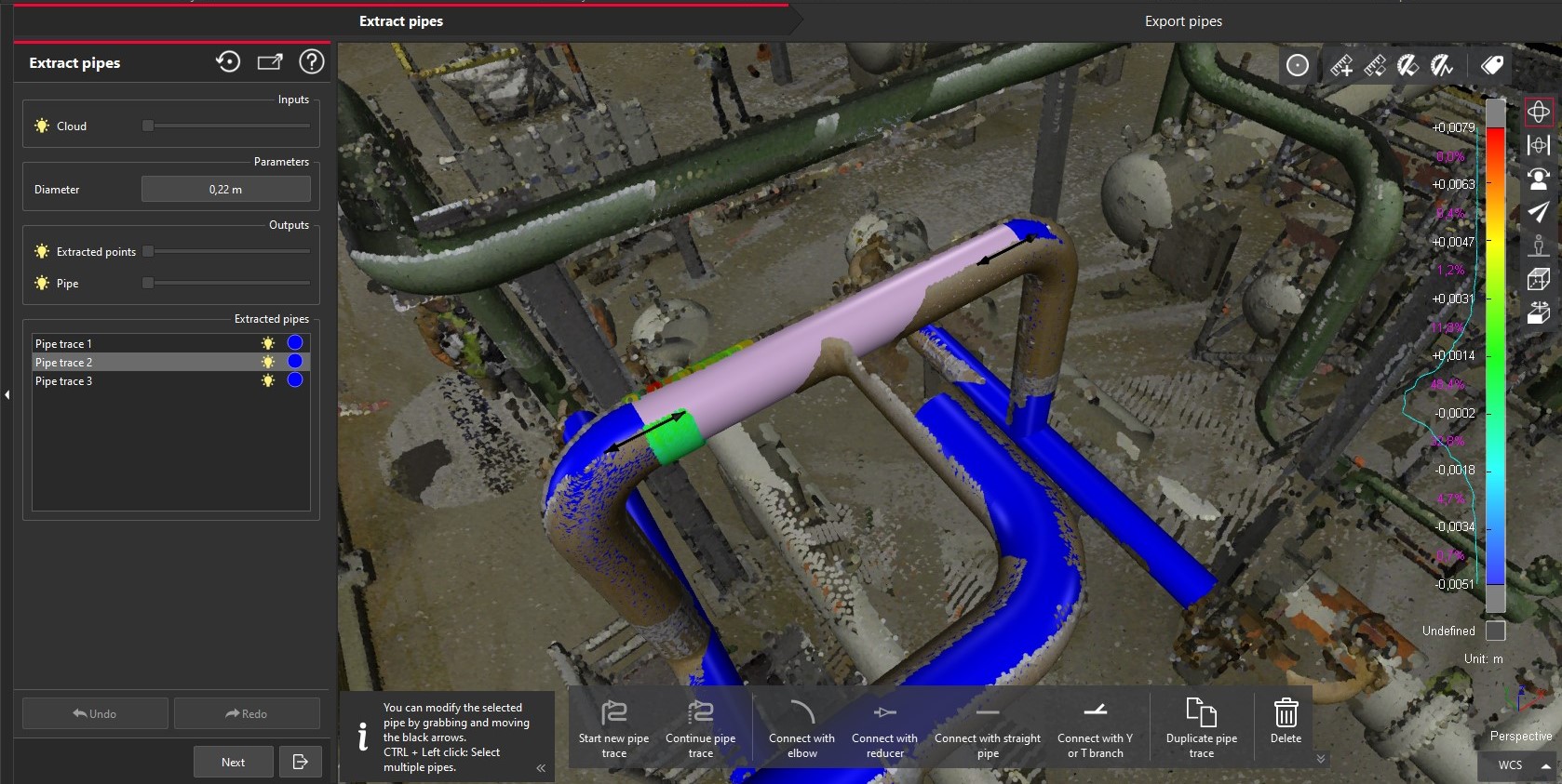
Activate the new mode Connect with branches (hotkey 4)
Click on the straight pipe (secondary trace) to connect
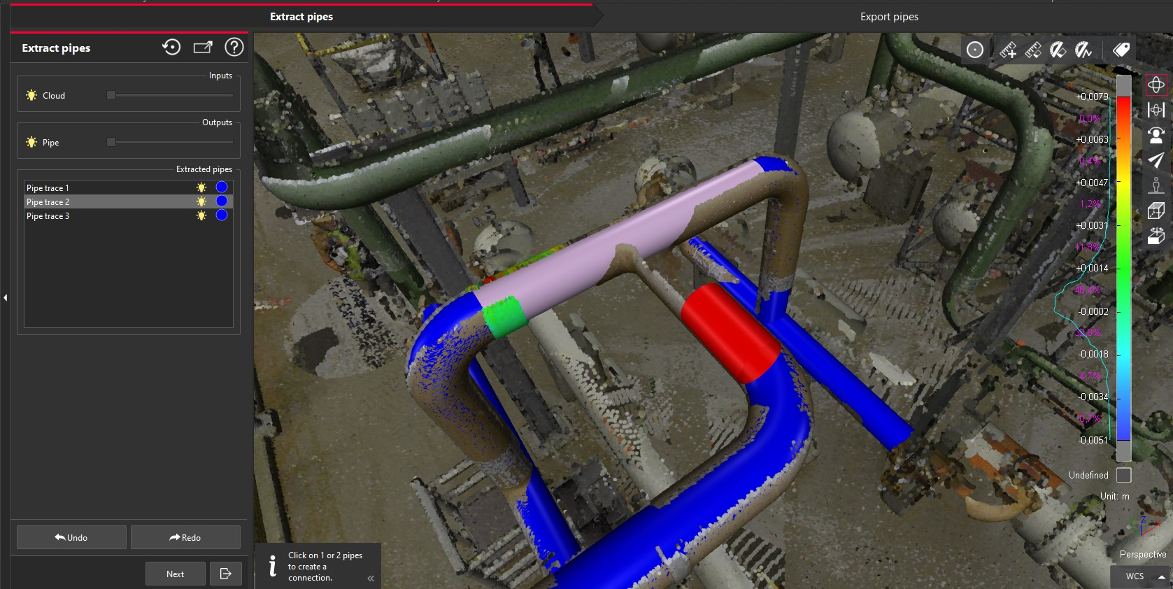
Click ENTER
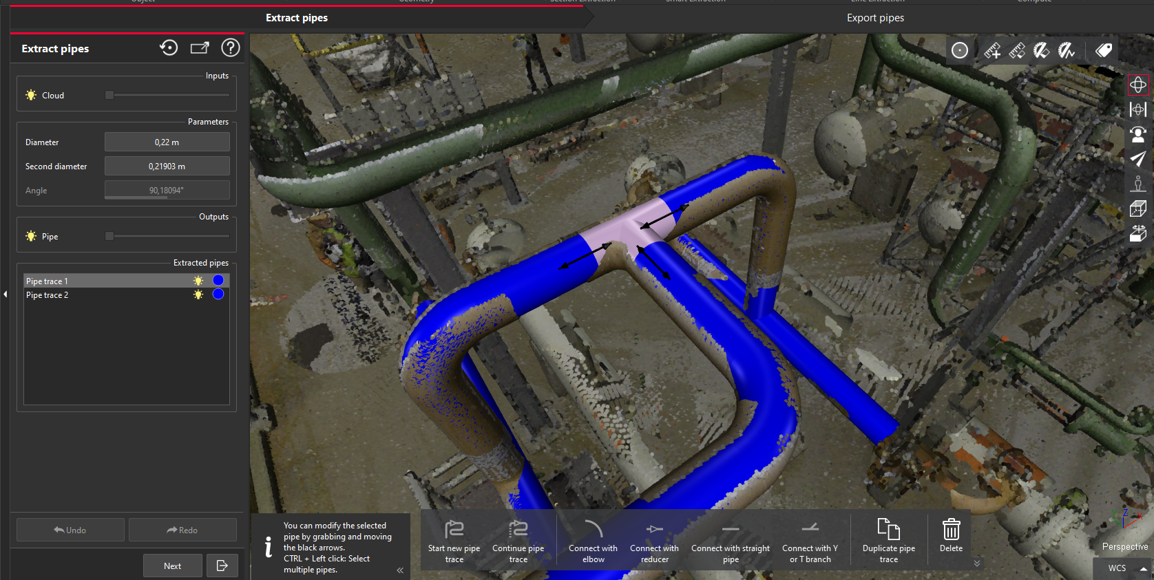
The branch is automatically created
The editing arrows are available to allow the user the adjust the size of the branch connector
The two traces are merged in a single trace in the Scan to Pipe project.
Adding a branch at the end of two traces
Select the extremity of the main trace, the “reference” (the segment must be extended straight)
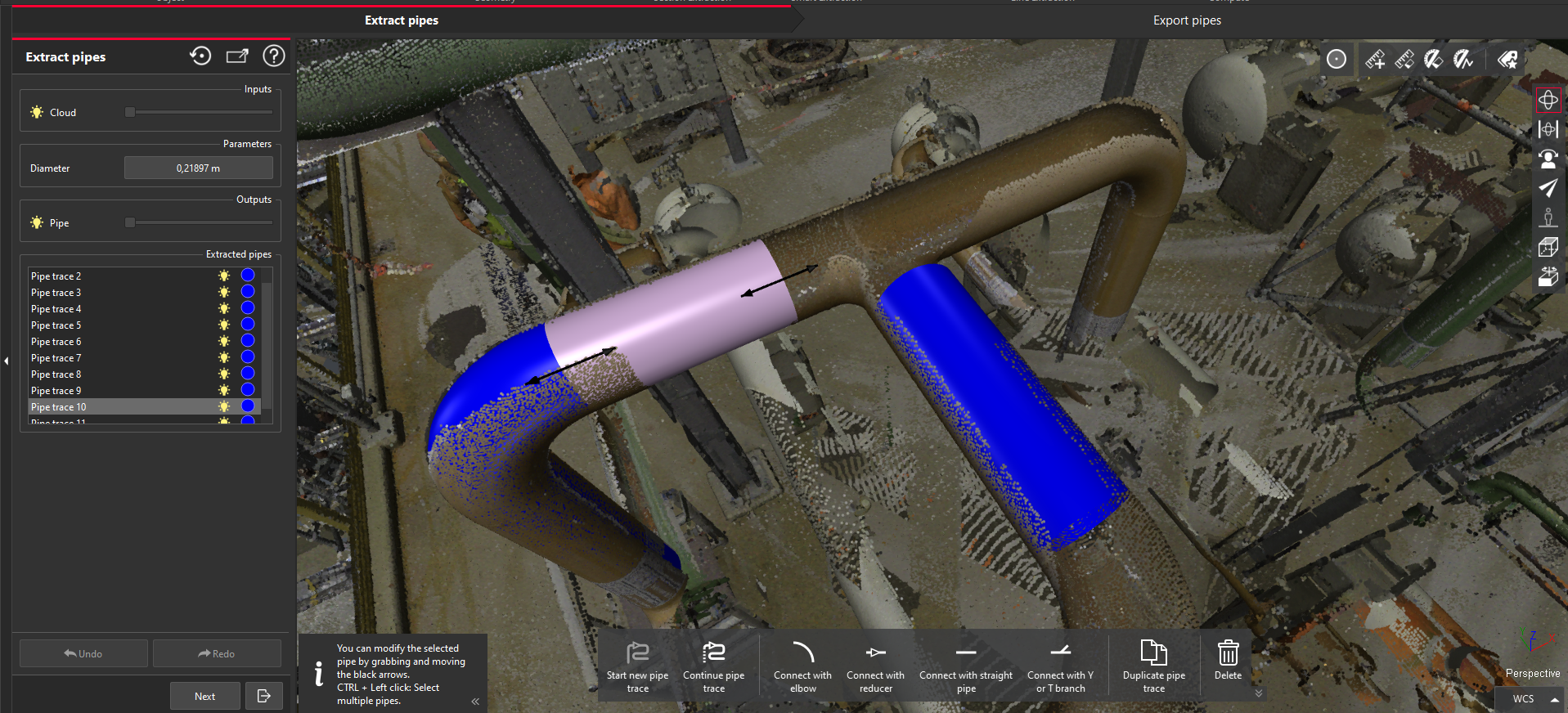
Activate the new mode Connect with branches (hotkey 4)
Click on the extremity of the secondary trace
Click Enter
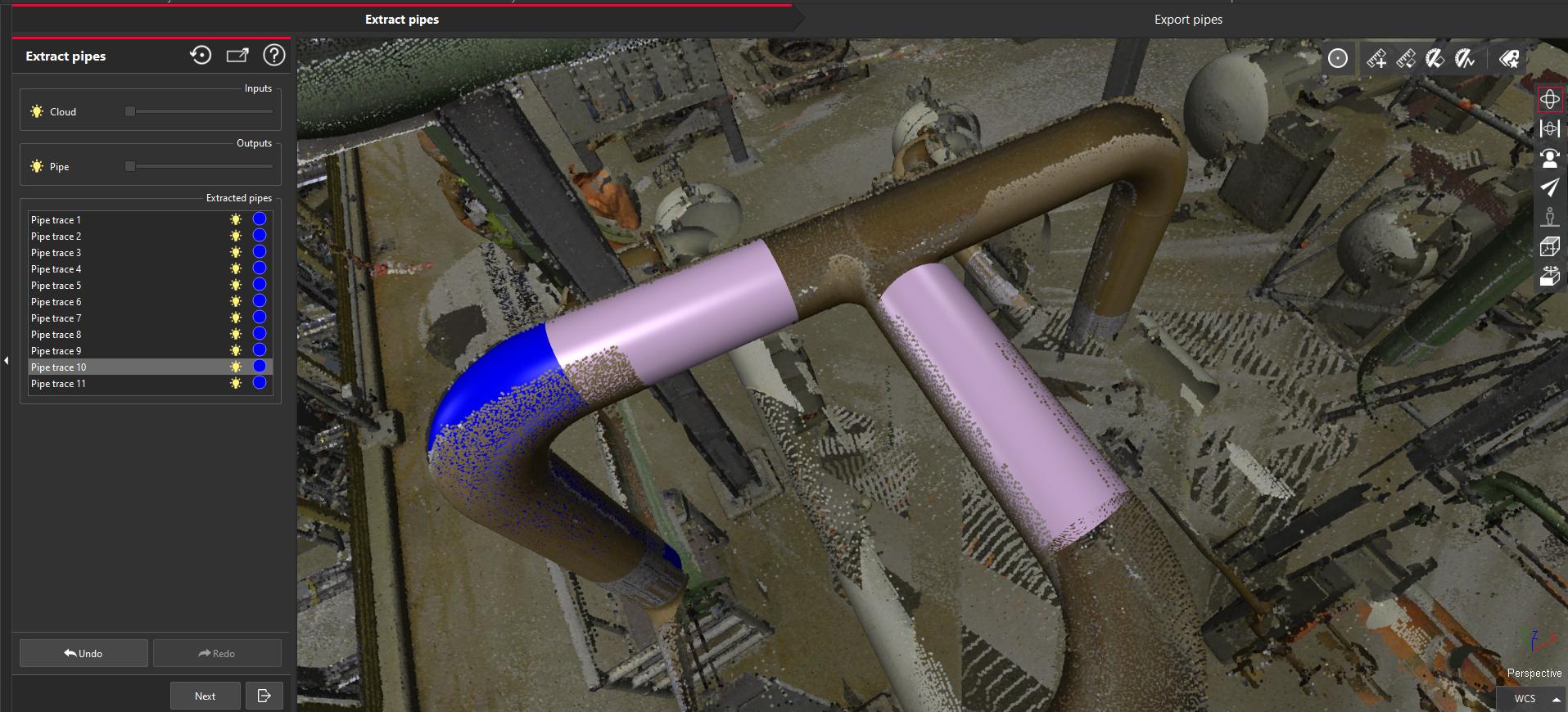
The branch is automatically created
The editing arrows are available to allow the user the adjust the size of the branch connector.
Once, the branch is placed, the trace can be extended.
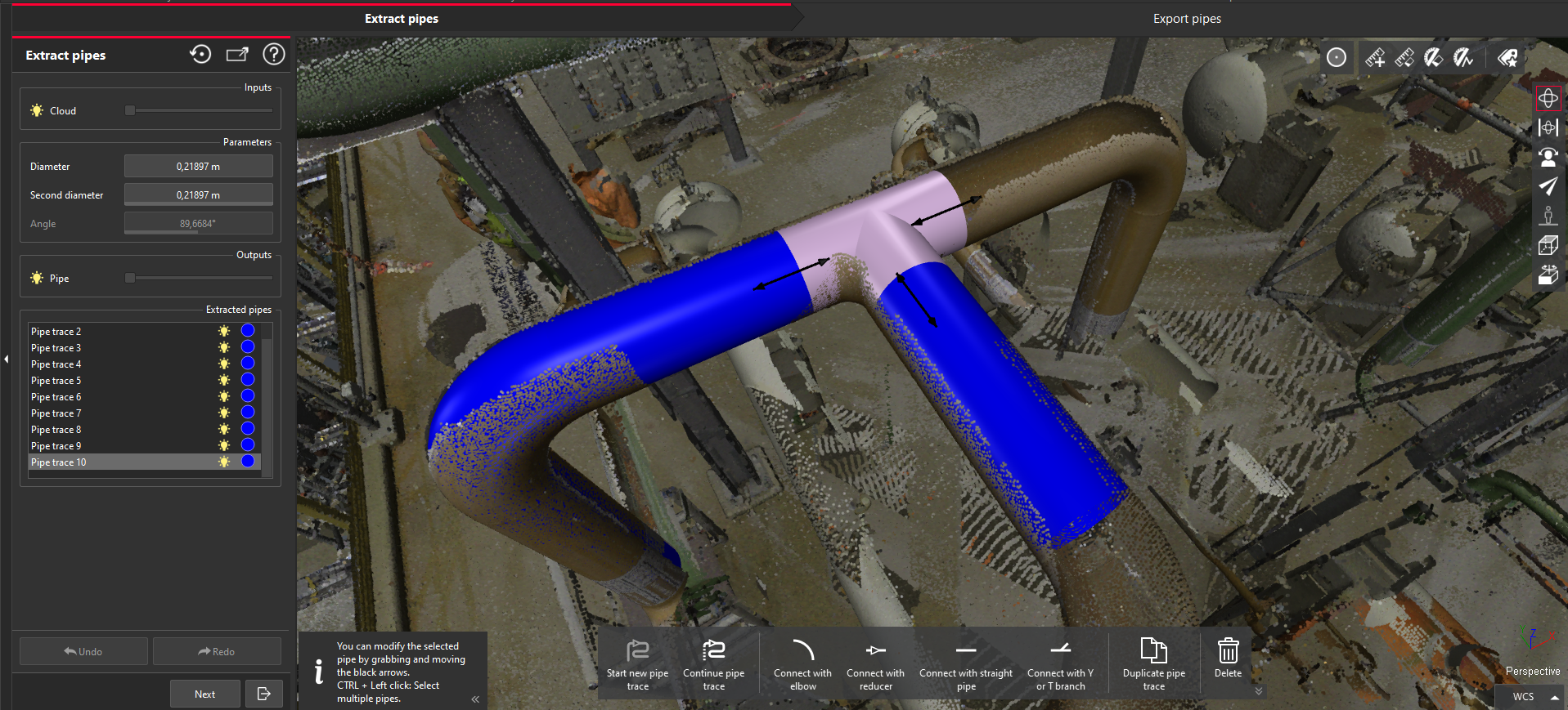
Like the other pipe components, the branches:
Can be edited:
From the dialog with numerical values: diameter (Extract) and thickness (Export).
Within the 3D scene with the arrows.
Can be exported with a specific ifctype to keep the branch information during export to BIM type model (ifc format): ifcflowfitting
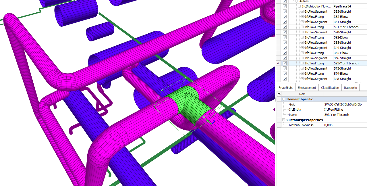
New Auto-fitting for elbows and reducers
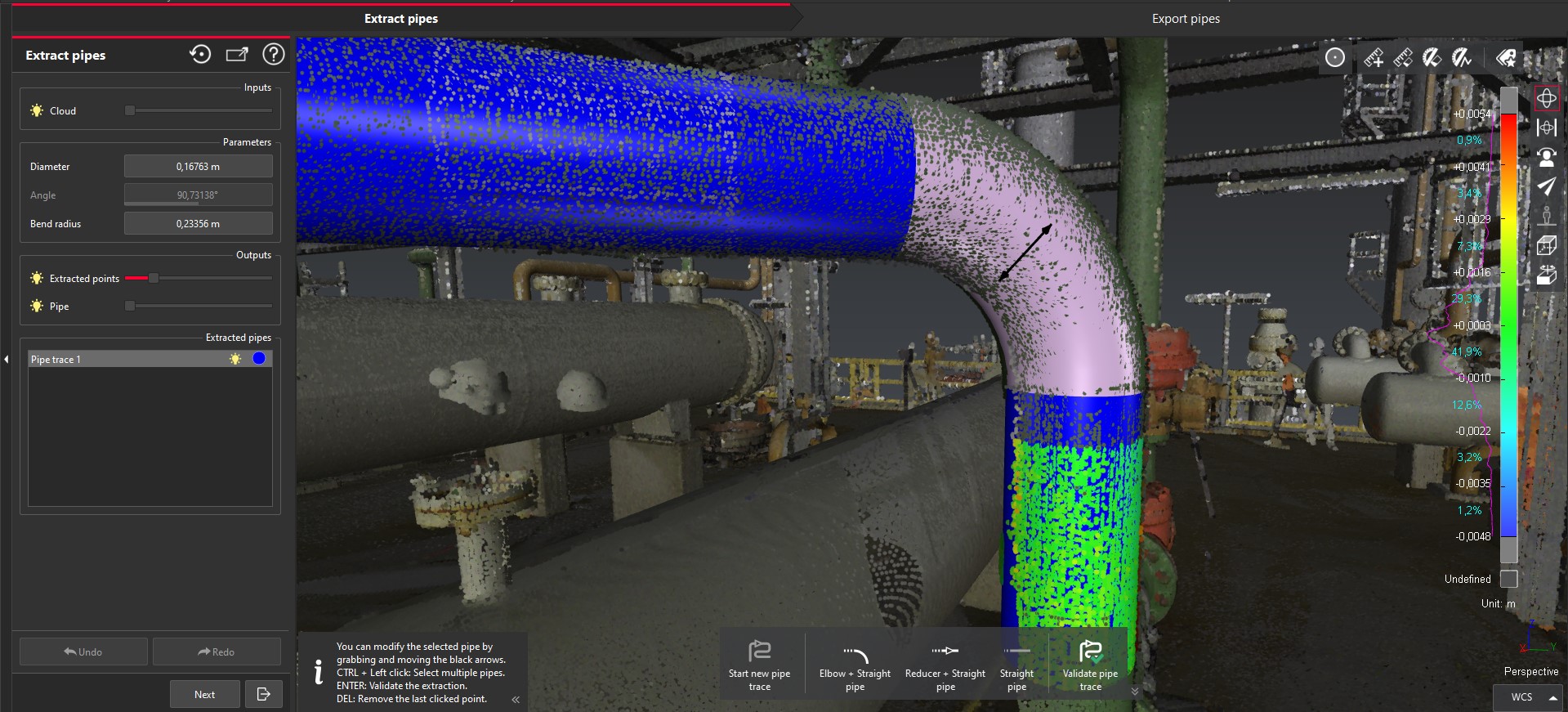
During the semi-automatic creation of a trace, the extraction has been significantly improved with the addition of auto-fitting for reducers and elbows. Users will immediately benefit from better performance of the extractor and accuracy of the fitted components, thus reducing manual editing and saving time.
The process for creating a trace is unchanged. The user will have an existing straight run, then double click on the next straight portion beyond the reducer or elbow. Now, the elbow or reducer will be fitted automatically along with the next straight portion.
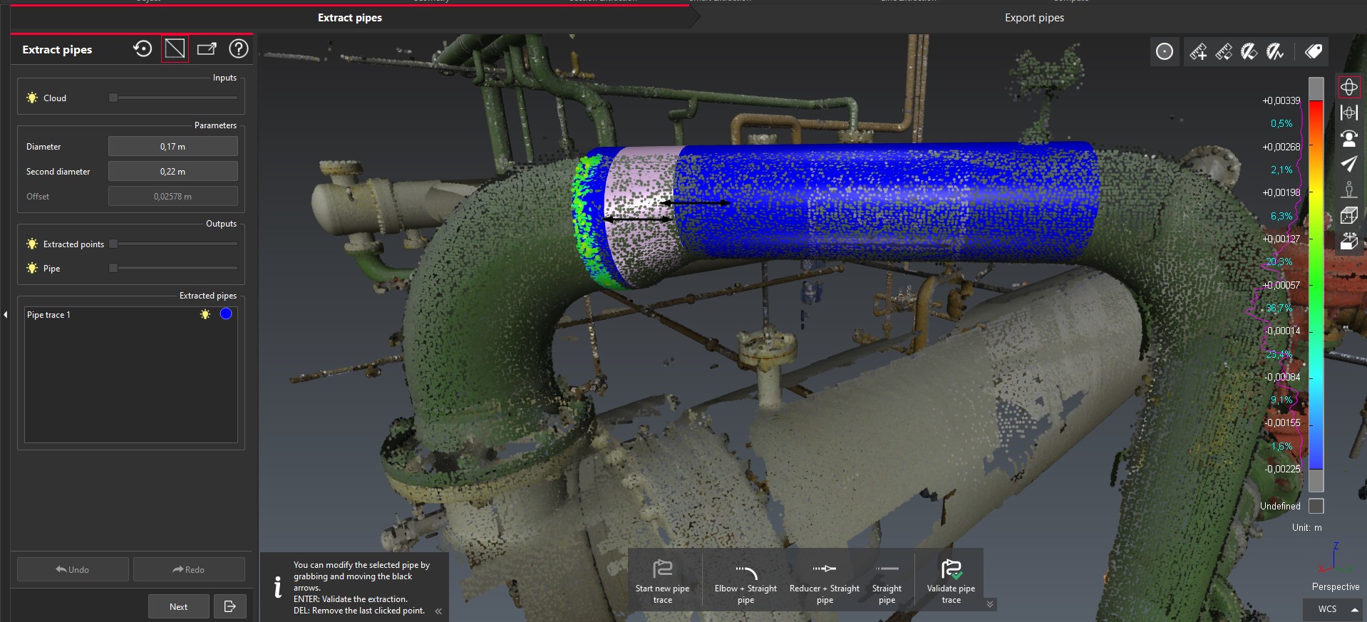
Duplicate a trace
Users can now copy a trace in order to rapidly duplicate a section that is repeated throughout the environment to save the user time and avoid unnecessary rework, or in situations where one repetitive element is lacking sufficient point density for fitting.
Select a trace.
Click on Duplicate a trace.
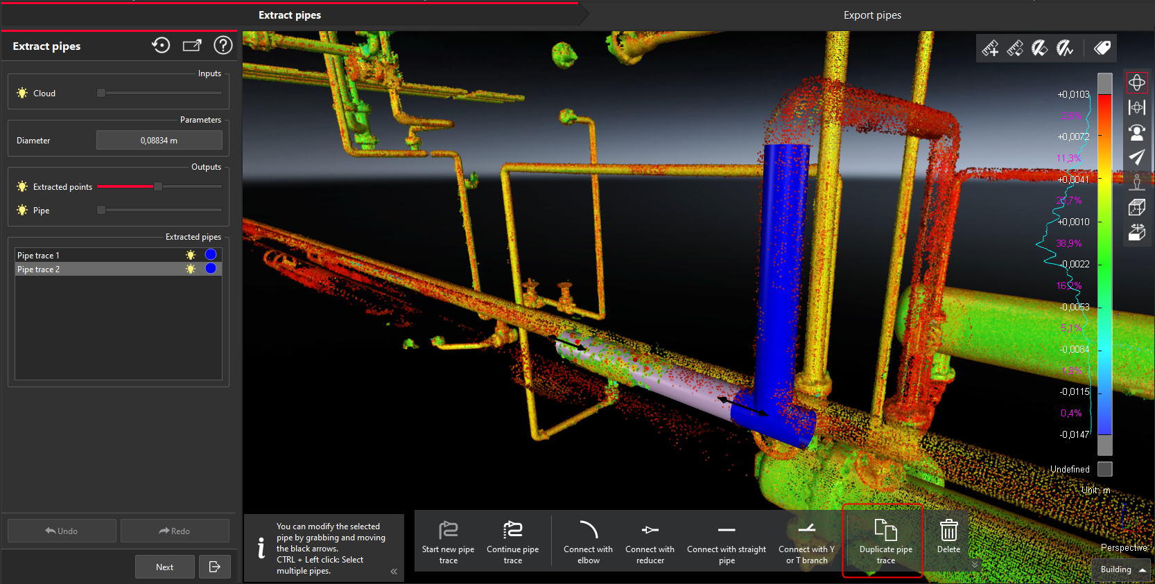
Automatically, a copy is created and the “free move” tool is enabled to allow the user to position the new trace as needed.
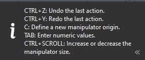
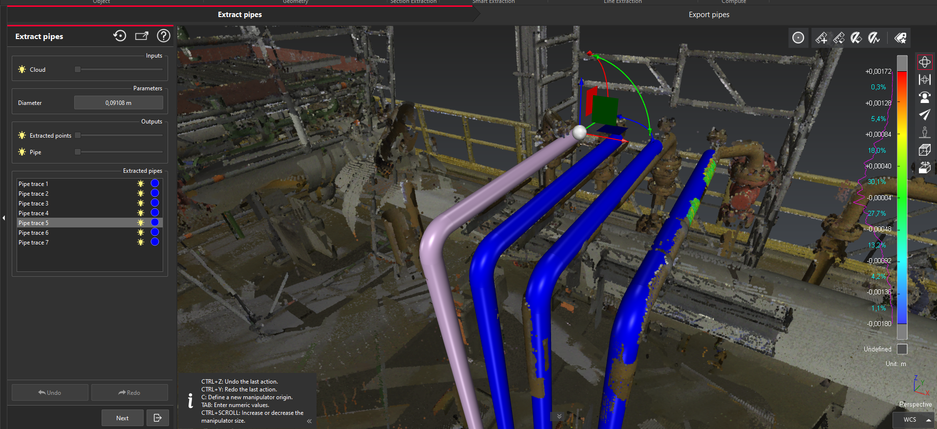
Follow the instructions to create the copy of the trace in a 3D environment. The “duplicate tool” widget is the same tool as the Free Move command in the application.
Users can undo and redo actions within the duplicate a trace tool.
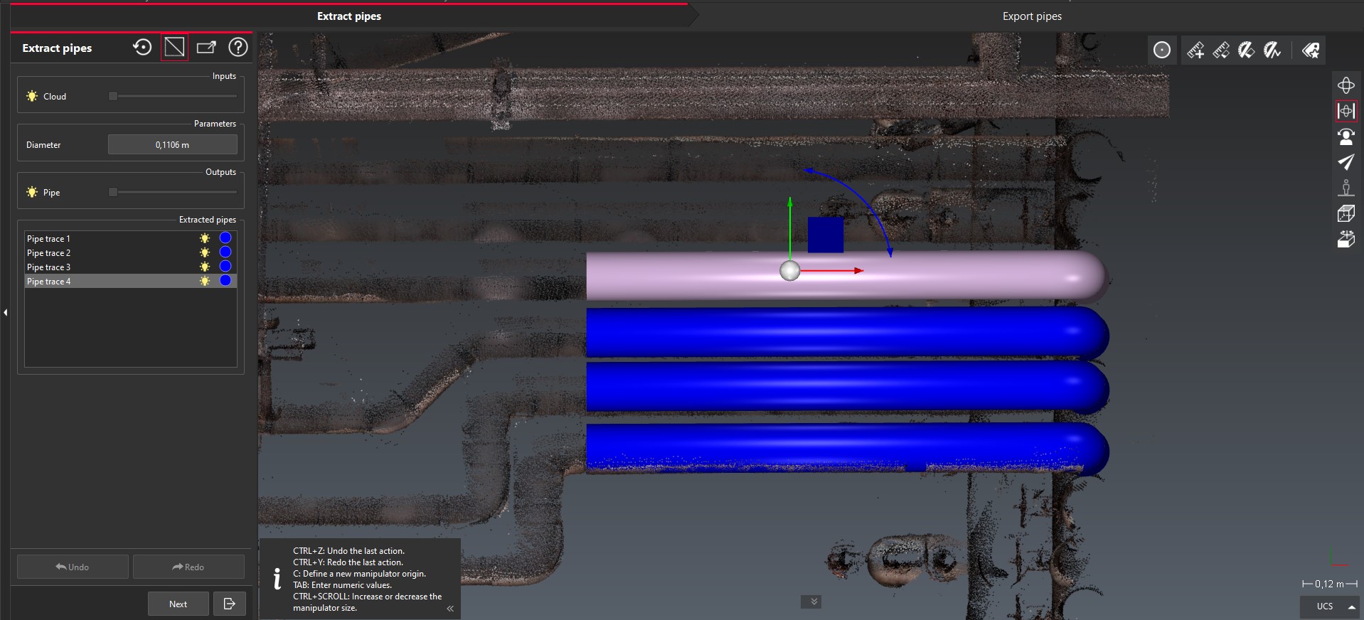
This new feature is relevant in situations when a portion of multiple traces are identical and parallel. In that case, it is recommended to create the common portion first, then to duplicate the identical portion, position it and, finally, to continue each separate trace beyond the identical portion. In addition, this new mode can be useful when the point cloud is very sparse in the area of interest, which is common in very dense piping zones.
New export options
Cyclone 3DR 2024.1 offers two new export options for pipe models as described below.
“Table of pipes” information [CSV]
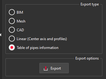
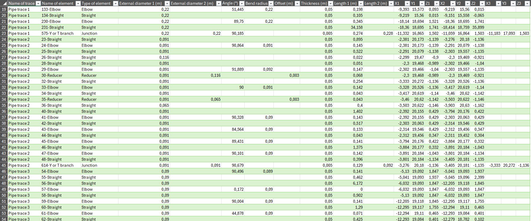
The CSV format is now supported from the Export step of the Scan to Pipe workflow and enables the creation of a table of pipe information. This new export can list all the objects (name and type) and their geometric information (diameters, thickness, coordinates, angle-if any).
This export capacity is complementary to the other formats and allows new possibilities such as QA/QC verification of the model and calculation of quantities to give more information to the end-users.
Option to export textured mesh models [OBJ, GLB, FBX]
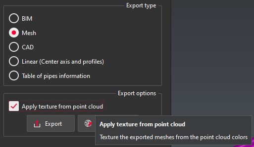
A new option is available to allow the creation of a texture from the point cloud colors when exporting the model to a mesh with a format that supports textures (obj, glb, fbx).
This option offers time saving and a direct way of export textured mesh for Scan to Pipe workflows.
User Interface improvements
Undo / Redo
During both extraction and export steps of the workflow, an undo/redo is now available from the dialog box. Those commands are also accessible with the usual shortcuts CTRL+Z / CTRL+Y.
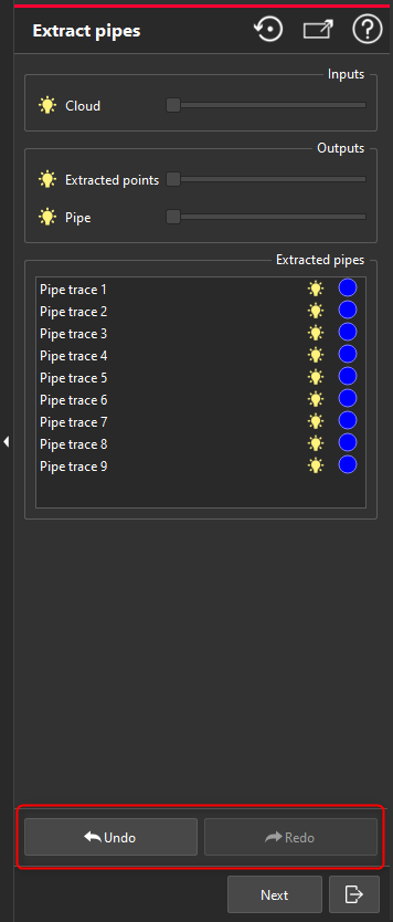
Hotkeys
New hotkeys are presented to users in the extraction step. Use of the hotkeys depends on what stage of the workflow the user is at.
Hotkeys | In the main 3D interface / No selection | In the main 3D interface / With selection | During pipe extraction |
|---|---|---|---|
+ | Start new pipe trace | ||
C | Continue pipe trace | ||
1 | Connect with “Elbow” (selection of an extremity is required) | Enable “Elbow+ Straight pipe” mode | |
2 | Connect with “Reducer” (selection of an extremity is required) | Enable “Reducer + Straight pipe” mode | |
3 | Connect with “Straight part” (selection of an extremity is required) | Enable “Straight pipe” mode | |
4 | Connect with “Y or T branch” (selection of a straight part is required) | ||
D | Duplicate the selected trace | ||
Enter | Validate the trace | ||
Del | Delete the selected component |
Multi selection of traces
Within the extraction step of the scan to pipe workflow, it is now possible to select multiple traces from the treeview or from the 3D Scene to edit in bulk. These multi-selected pipes can be deleted or have properties like their diameter changed.
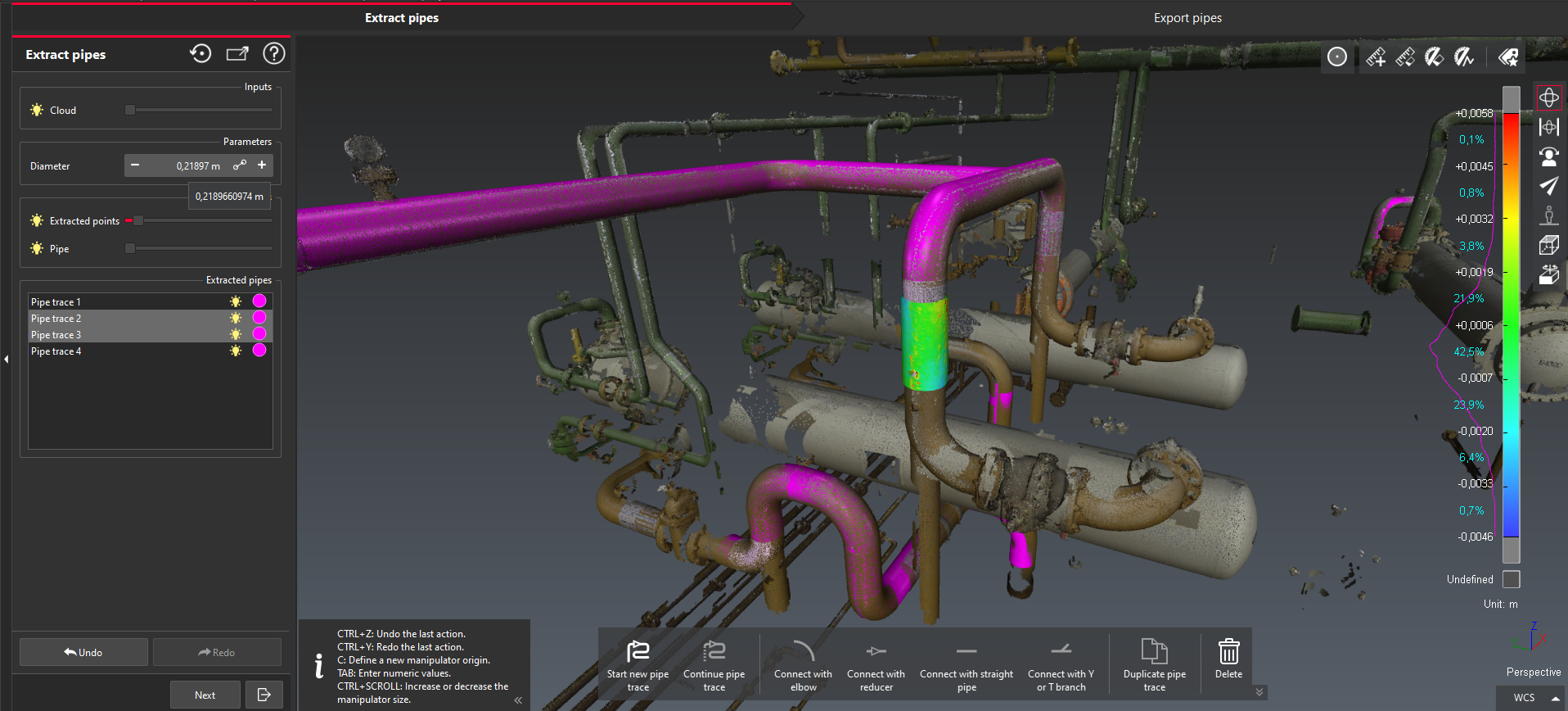
Selection for export
Users can now choose which traces to export rather than having to export all. To export a sub-selection of the piping model, users can activate or deactivate the check boxes . The Export all / Export none buttons are helpful to save time in the selection.
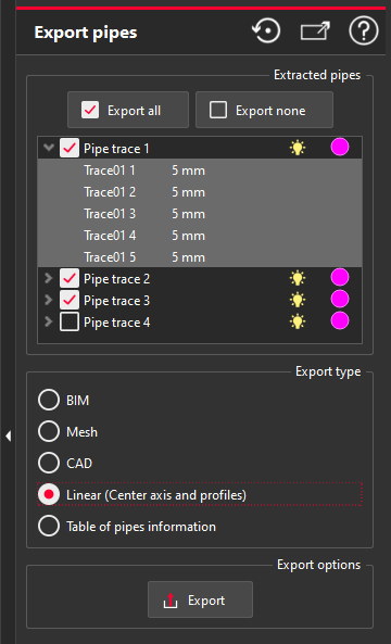
Better synchronization of 3D scene
In the Export step of the scan to pipe workflow, the treeview and the 3D scene are now permanently synchronized. When an object is selected in the treeview, it is select in the scene and vice versa. This gives users a better 3D experience and makes it easier manipulate objects in the 3D scene based on parameters that are available in the treeview.
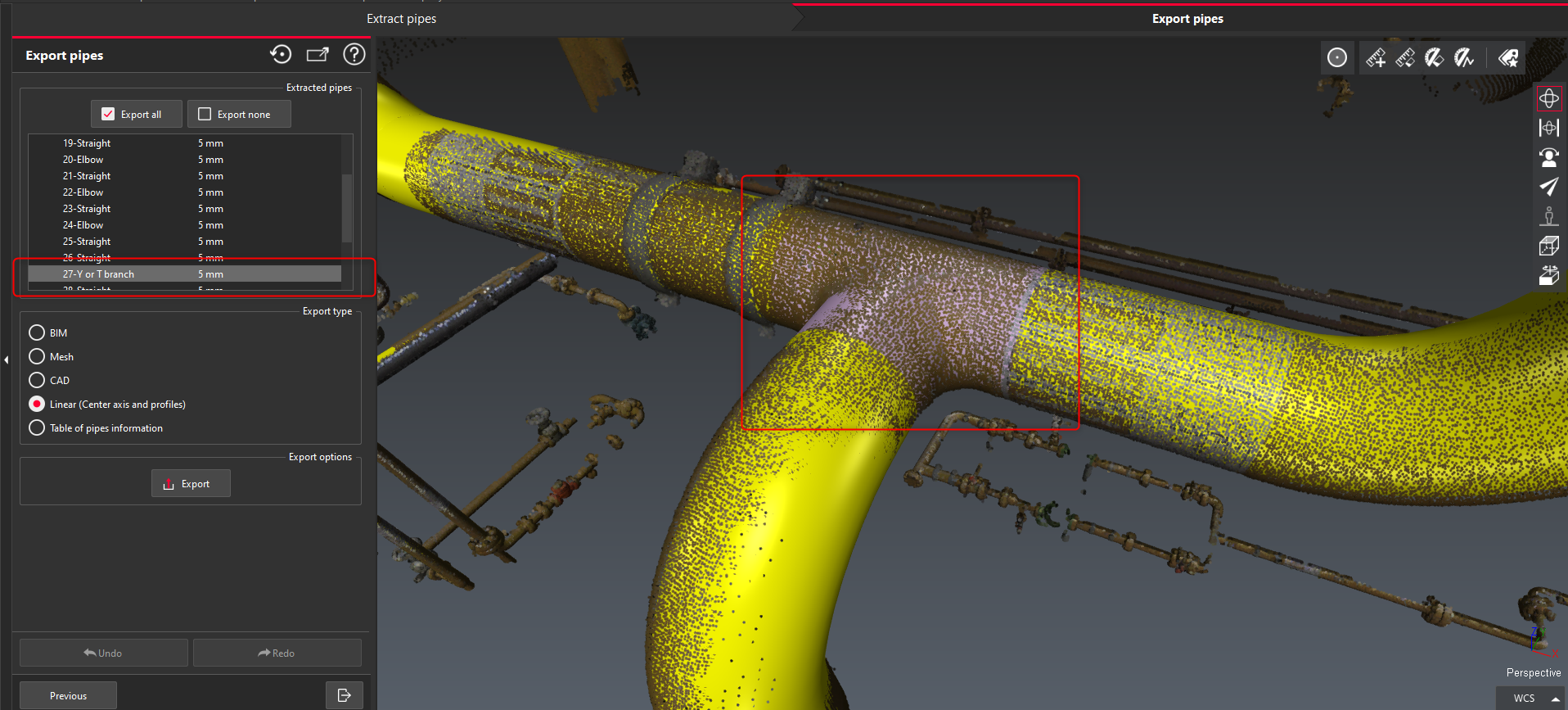
Point cloud classification
Updated classification engine
Since the first release of point cloud classification in the 2021.2 version of Cyclone 3DR, the engine has been improved on a regular basis, including the time performance of execution. With the 2024.1 version of the product, a new classification engine has been introduced which offers better performance in comparison to the previous 2024.0 version of Cyclone 3DR. The time of computation is now reduced by approximately 20%.
To enable the new engine, the installation of the components is unchanged from the previous version.
Install Cyclone 3DR 2024.1 application
Execute Auto-Classification for the first time to download and install the classification package (including CUDA drivers and new models)
Restart Cyclone 3DR application
This feature is available to users with the Survey, or AEC, or Plant or PRO licenses.
New model for Plant application
With the new classification engine, a new model is now available which has been trained for piping environments. For the first version of the model, the focus has been made for 6 different classes:
Straight cylinders
Bend cylinders
Reducer cylinders
Connections
Valves
Undefined
One useful application of this new plant classification model is for cleaning the data prior to modeling (meshing, Scan to Pipe or analysis).
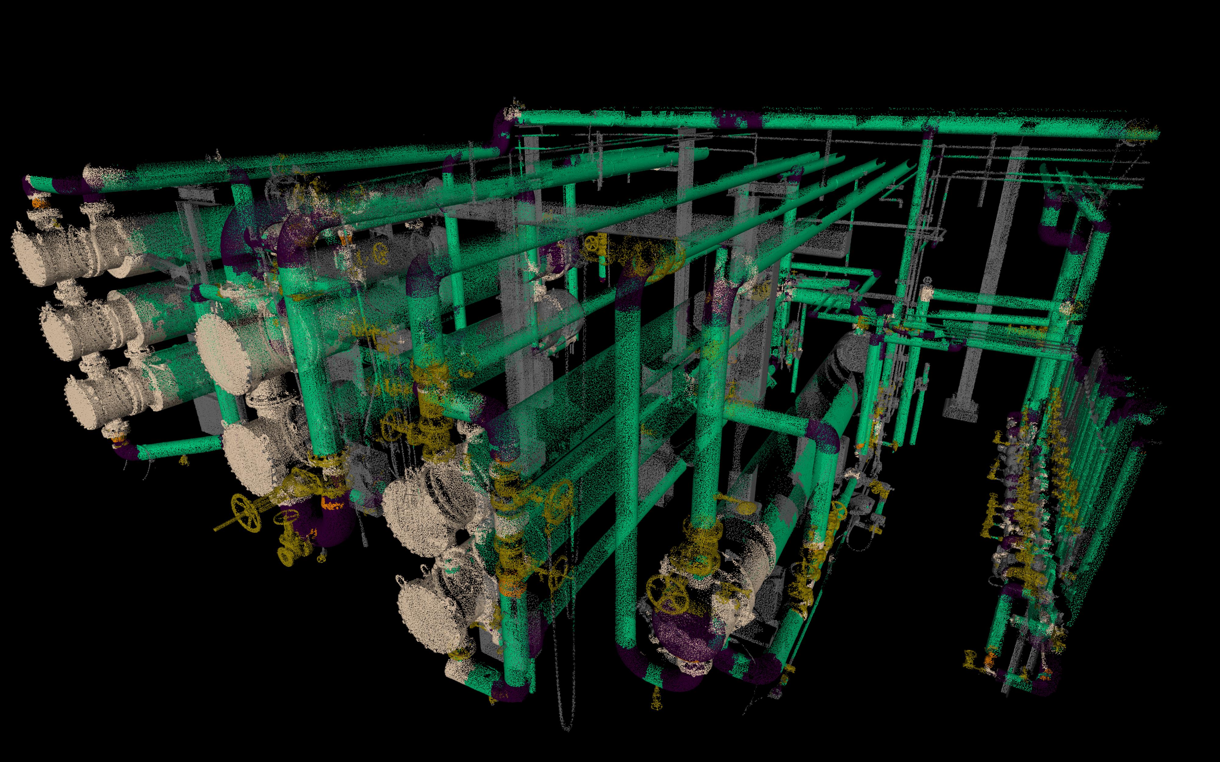
Typically, the user will remove the undefined points from a point cloud data before a Scan to Pipe job, to remove noise, improve the visualization of the piping assets and simplify the extraction. Even if the user prefers to keep the undefined points before the extraction process, it is extremely useful to visualize the classification representation for a better understanding of the digital reality.
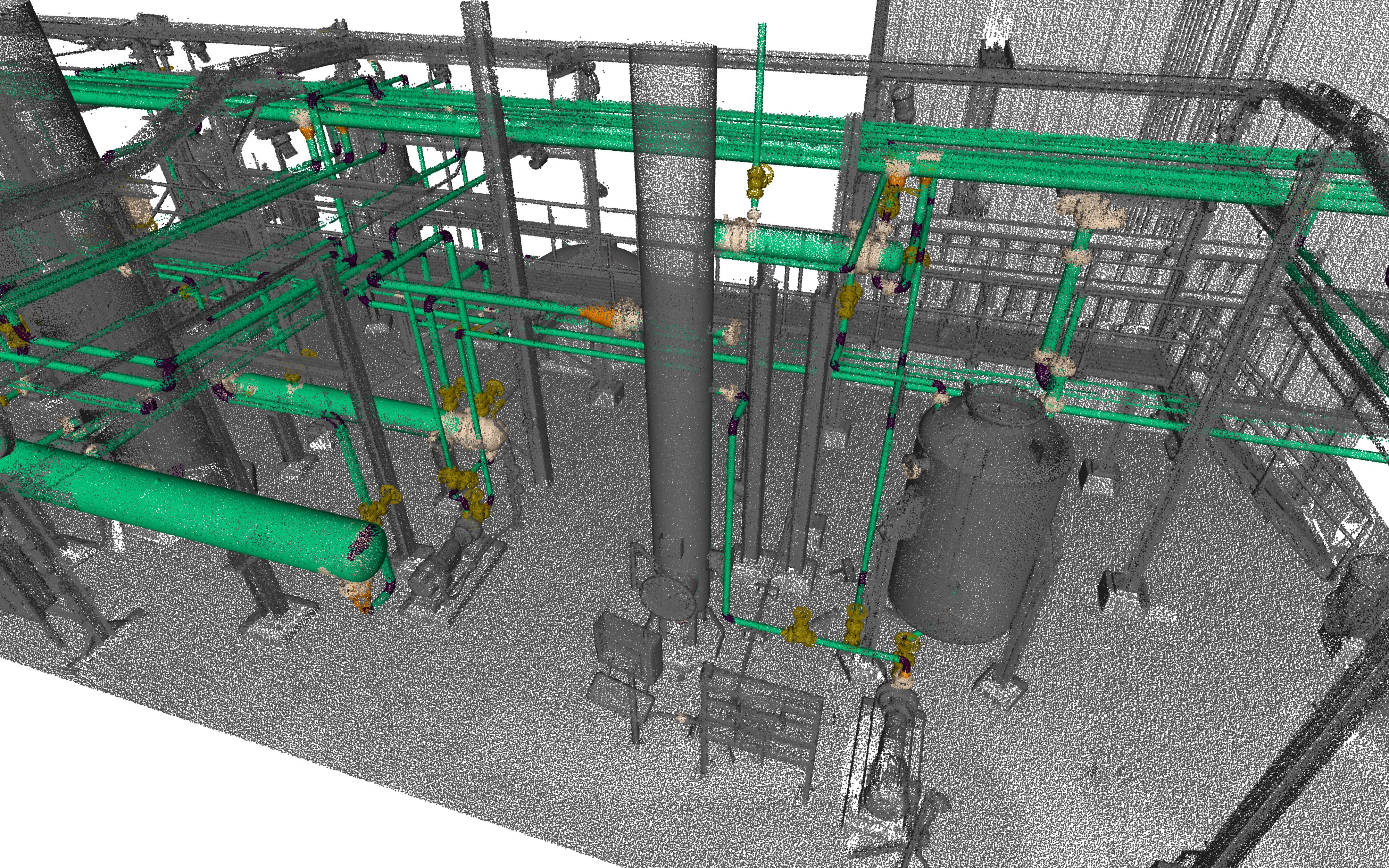
This feature is available to users with the Survey, or AEC, or Plant or PRO licenses.
Statistics
Within Cyclone 3DR 2024.1, a new statistics feature is available in the Analysis menu. Statistics allow for advanced reporting for all analysis workflows in the application.
Execute an analysis workflow that creates an inspected model as an output. The inspected model can be a mesh/BIM/CAD/Geometry analysis, a point cloud, a grid of points (Example: Gridded Inspection), a polyline.
Select the result of the analysis (from the treeview or the 3D scene).
Select Statistics from the Analysis menu.
The 3D scene is automatically hidden to display the histogram distribution of the analysis and the most relevant statistic values.
Modify the report to suit the project needs.
Edit the properties of the histogram (color, color with gradient, cumulative graph, etc.).
Create a new report chapter.
Export a detailed report that can enable the export of a discretized CSV table from the report editor, to let the user perform more advanced statistic analysis on his own.
Click OK to validate the Statistics operation.
Open the Report Editor, to visualize and prepare the report (PDF or CSV).
This feature is useful to complete advanced analysis, in particular when it is necessary to prove a detailed distribution in the situation of a control relying on standards or a norm. In general, the new command is a way to amend traditional Cyclone 3DR analysis with additional information.
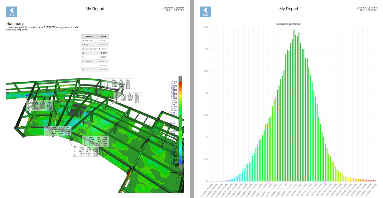
Note for point clouds: this new feature works with the inspection attribute on the points.
It is necessary to display the inspection value of the object before executing the Statistics feature.
However, this new command unlocks the capacity to create statistics for other scalar values/attributes like the intensity, the timestamps or the density (please refer to https://hexagon.atlassian.net/wiki/spaces/RCD/pages/edit-v2/44135007535#Separate-by-attributes).
To do such a statistic control, appropriate scalar value of the object (representation feature from the treeview) must be displayed before executing the Statistics command.
This feature is available to users with the Standard licenses.
LGSx integration updates
Cyclone 3DR 2024.1 continues to make improvements in handling LGSx files including support for more features and functions without converting LGSx to the Cyclone 3DR native format, displaying trajectories and supporting LGSx in the Cyclone 3DR Free Viewer.
Support for native LGSx images
Users may now stream pano images from LGSx files without any conversion steps. This improvement offers users the possibility to navigate through images and to display the images in the 3D Scene for all the workflows that do not require conversion of the 3DR native format.

Immediately, users will be able to:
Conduct visual reporting of the as-built via LGSx, with Visual Notes.
Utilize Virtual Surveyor to extract based on point selection with the help of the images.
Utilize all recently released navigation tools from Cyclone 3DR 2024.0.

Notes on LGSx image usage
The first uploading stage is longer when the user selects the option because all the images are pre-loaded. Images might not be necessary for some workflows. In such case, it is recommended to uncheck the option.
The streamed images are loaded in cache and not saved in a folder when the 3DR project is saved. It is possible to access to the streamed images later when the project is opened again, as soon as the LGSx file is linked to the 3DR project.
To execute texturing features that require images, it is mandatory to convert the images from the LGSx project. Requirements are detailed in this chapter: https://hexagonmi.atlassian.net/wiki/spaces/RCD/pages/edit-v2/44135007535#Compatibility-with-native-JetStream-point-clouds
It is possible to have both streamed images and converted images in a Cyclone 3DR project:
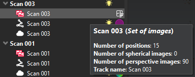
Support for LGSx Trajectories (Tracks)
Automatic import
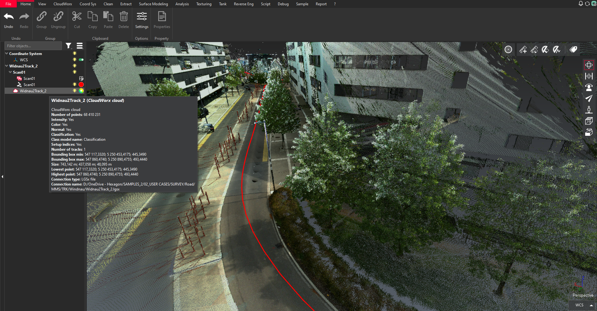
When a LGSx project is imported into Cyclone 3DR 2024.1 (without any conversion step), the trajectories/tracks are automatically imported and converted into trajectory objects in Cyclone 3DR for all mobile scanner projects (BLK mobile sensors and TRK series).
Users no longer have to go through a conversion step to the Cyclone 3DR native format to use the trajectory assets in Cyclone 3DR. Further, users may now:
Create clipping slices from the curved axis of the trajectory
Utilize the trajectory within the scripting workflow with more automation
This improvement does not impact the performance of the experience since trajectories are very light assets.
This feature is available to users with the Standard licenses.
Create groups from trajectories
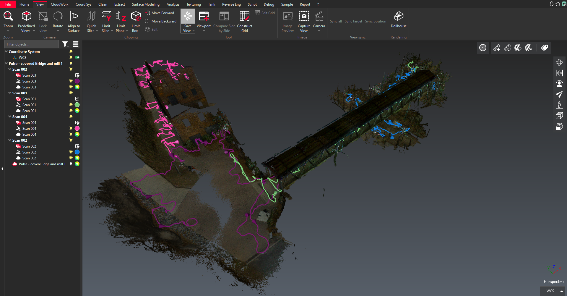
Upon import of an LGSx file containing trajectories, users can now split the project into groups based on the trajectory objects. That means that after the conversion of the LGSx project, each group is composed of:
An isolated point cloud
A set of images (streamed or converted according to the choice of the user - described in the previous chapter)
A trajectory
This improvement allows users to quickly isolate and focus on the relevant section of the data.
This feature is available to users with the Standard licenses.
LGSx supported in Cyclone 3DR Viewer
Cyclone 3DR Viewer now supports the capacity to stream LGSx projects with the same options and capabilities as the regular Cyclone 3DR application including:
Point Cloud
Images
Trajectories
Cyclone 3DR Viewer is available for free on-demand via the following platform: https://leica-geosystems.com/products/laser-scanners/software/leica-cyclone/leica-cyclone-3dr/leica-cyclone-3dr-download
This feature is available to users with the free Cyclone 3DR Viewer.
Point Cloud attribute updates
Cyclone 3DR 2024.1 now stores and exposes additional point cloud attributes for better management of point cloud information, optimized cleaning or usage of point cloud data for analysis and reporting.
All the Point Cloud attribute features are available to users with the Standard licenses.
Separate by attributes
A new smart segmentation feature is exposed within Cyclone 3DR 2024.1 which allows users to segment a section of the point cloud by attribute. This new feature offers a harmonized way to segment with the following attributes:
Attributes based on indexes:
Classification: segmentation by class
Return Type: new supported attribute in Cyclone 3DR 2024.1 described here https://hexagon.atlassian.net/wiki/spaces/RCD/pages/edit-v2/44135007535#Support-of-return-type-values
Attributes based on scalar values or color gradient:
Intensity: segmentation by value ranges
Inspection: segmentation by value ranges of an inspection analysis executed in Cyclone 3DR
Timestamps: segmentation by value ranges
Density: segmentation by value ranges, computed with one of the 2 script functions: ComputeDensityFromNearestPoints() or ComputeDensityFromSphere()
Separate by Attributes replaces and consolidates several old commands for the same purpose of point cloud segmentation. The following commands are deprecated.
Explode by Class
Scalar Steps
Scalar Range
The new point cloud segmentation workflow is as follows:
Select one point cloud
Execute Separate by attributes from the Clean menu
Select the appropriate attribute to segment the input point cloud.
By default, the visible attribute is the first one exposed.
Only the available attributes are exposed.
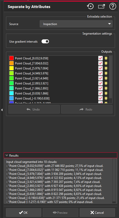
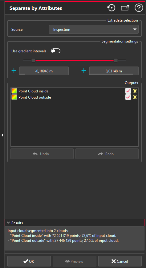
For scalar value-based attributes, toggle the Use gradient intervals toggle on and off to switch between selection modes
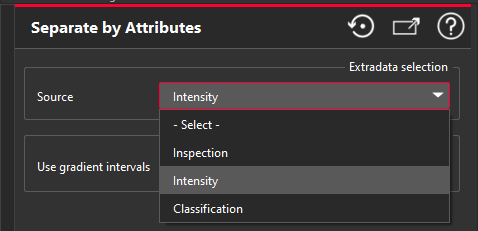 | 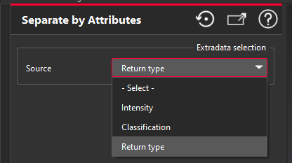 |
Two different interfaces are exposed to the users if the selected attribute is based on indexes or based on scalar values:
Index-based attributes menu
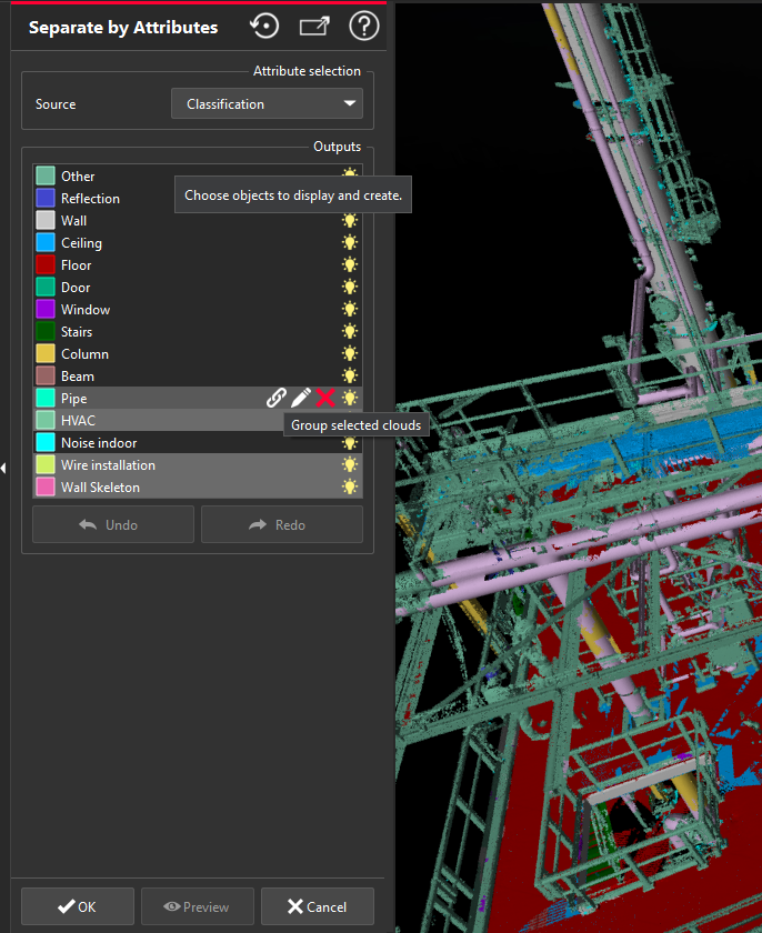
The list of the attributes is exposed with checkboxes to help the user to define the output point clouds.
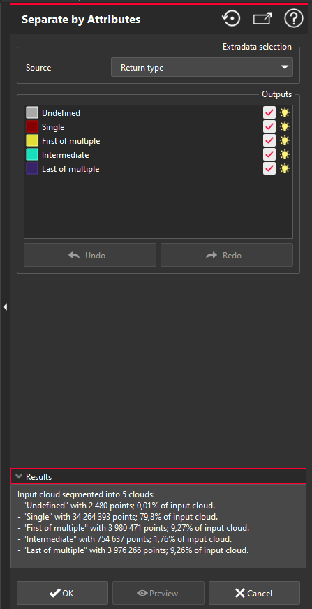
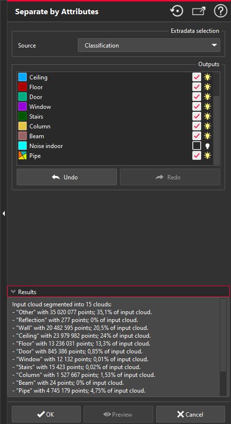
Scalar value-based attributes menu
If the color gradient is composed of ranges, it is possible to automatically segment according to the ranges, which simplifies the experience.
Alternatively, toggle off the Use gradient intervals toggle to expose a slider to define the range of values.
Once the point cloud is segmented by the methods above, users can make further adjustments to the outputs and visibility of the cloud.
Check box to define if the sub-cloud is saved as an output or not.
Bulb to manage the visibility of the sub-cloud in the 3D Scene.
Undo/redo
Using either the buttons at the bottom of the dialog or Ctrl+Z, Ctrl+Y.
Merge sub-selections (the attributes remain saved after merging)
Select multiple attributes and right click, select Group selected clouds
Rename sub-selections (from right click)
Remove sub-selections
Using the X button to the right of the attribute name
Support of return-type values
New attribute
Cyclone 3DR 2024.1 now supports return-type values (based on laser scanner patterns) with the formats LAS, LAZ and E57. The values are exposed as a new attribute of the imported point cloud, which unlocks a new representation.
This new feature is relevant for scanners that can provide return-type values, which are primarily Mobile Mapping Scanners (TRK series) and Aerial sensors.

The return type values are categorized in 5 groups:
Single
First of multiple
Intermediate
Last of multiple
Undefined
Return type is supported with Import and Export for LAS/LAZ and E57 formats.
The new segmentation tool Separate by Attributes is compatible with this new attribute. Users will now be able to efficiently and accurately clean the point cloud according these attributes. A typical application is the easy removal of vegetation to produce an accurate DTM.

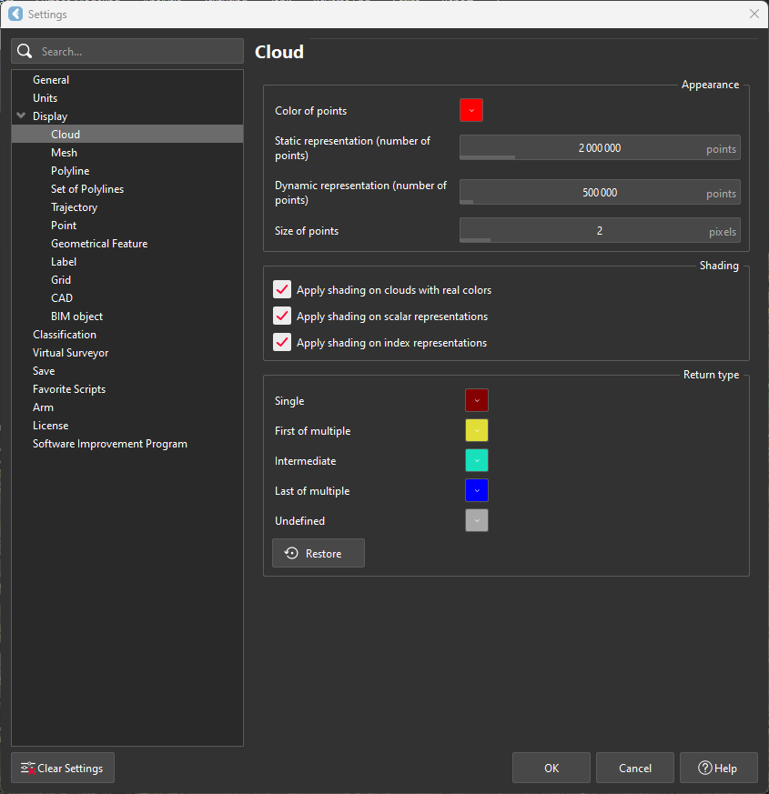
New settings
To support the new return-type values, new color parameters are exposed in the settings for the user to customize the representation. They are accessible in the Display > Cloud menu of the Settings.
Filter LAS/LAZ by attribute at import
In Cyclone 3DR 2024.1, users can now filter LAS/LAZ formats by certain attributes prior to importing to optimize their import and reduce the site of the data if unneeded for the application. LAS and LAZ data can be filters by:
Intensity
Classification
Return-Type
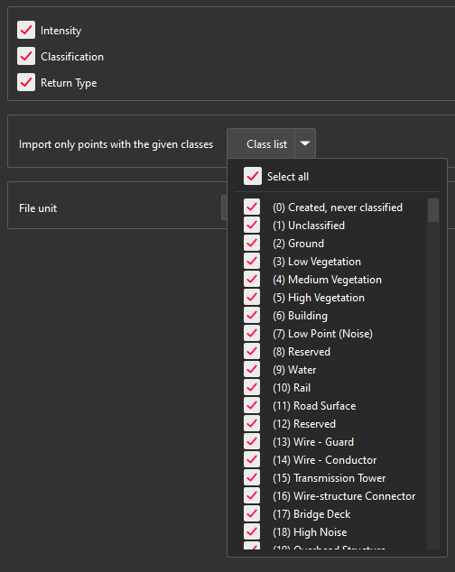
In addition to this first filtering level, when the classification is selected for import, it is also possible to filter by classes. This can further reduce the size of the data to import only the necessary points for the targeted application.
As an example, a user might not want to keep the vegetation for a DTM creation in Cyclone 3DR, as it is illustrated on the image below.
When an LAS or LAZ file is loaded, the user will be presented with a list of its attributes and can select or unselect them for import using check boxes.
Connect to Reality Cloud Studio updates
With Cyclone 3DR 2024.1, the point clouds that are streamed from Reality Cloud Studio, can store more attributes:
Timestamps
Classification
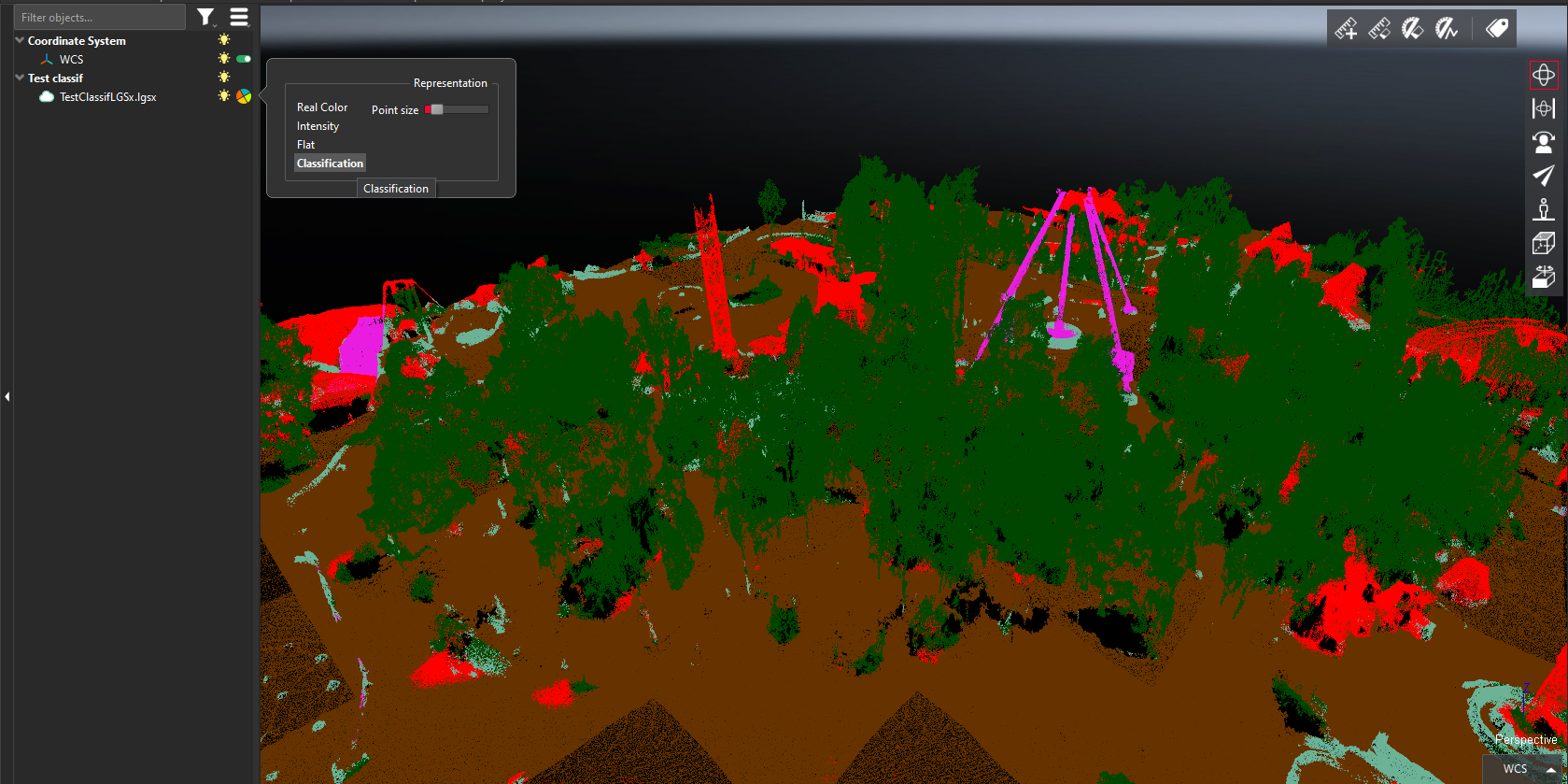
These attributes will be stored automatically if the native point cloud contains such information. It is possible to convert the point cloud and to keep timestamp and classification attributes which can be used to finish the workflow with the advanced segmentation tools of the application.
Within the 2024.1 version of Cyclone 3DR, note that only the classification attribute can be visualized from a streamed Reality Cloud Studio point cloud. The 'timestamps' attribute can be visualized after the conversion of the streamed object into a 3DR point cloud.
Reality Cloud Studio credentials are necessary to use the Connect to Reality Cloud Studio feature.
Improvement for Intensity and Inspection attributes
With the release of Cyclone 3DR 2024.1, it is now possible to store both intensity and inspection value attributes simultaneously. This improvement over previous versions of Cyclone 3DR ensures that users do not have to compromise on the information associated with their point cloud, offering them the widest possible scope of attributes to segment according to.
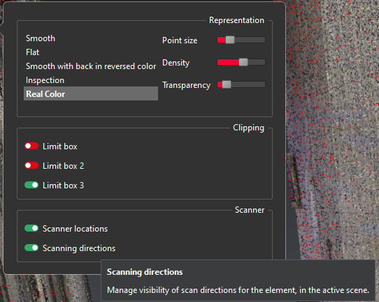
Scanning directions
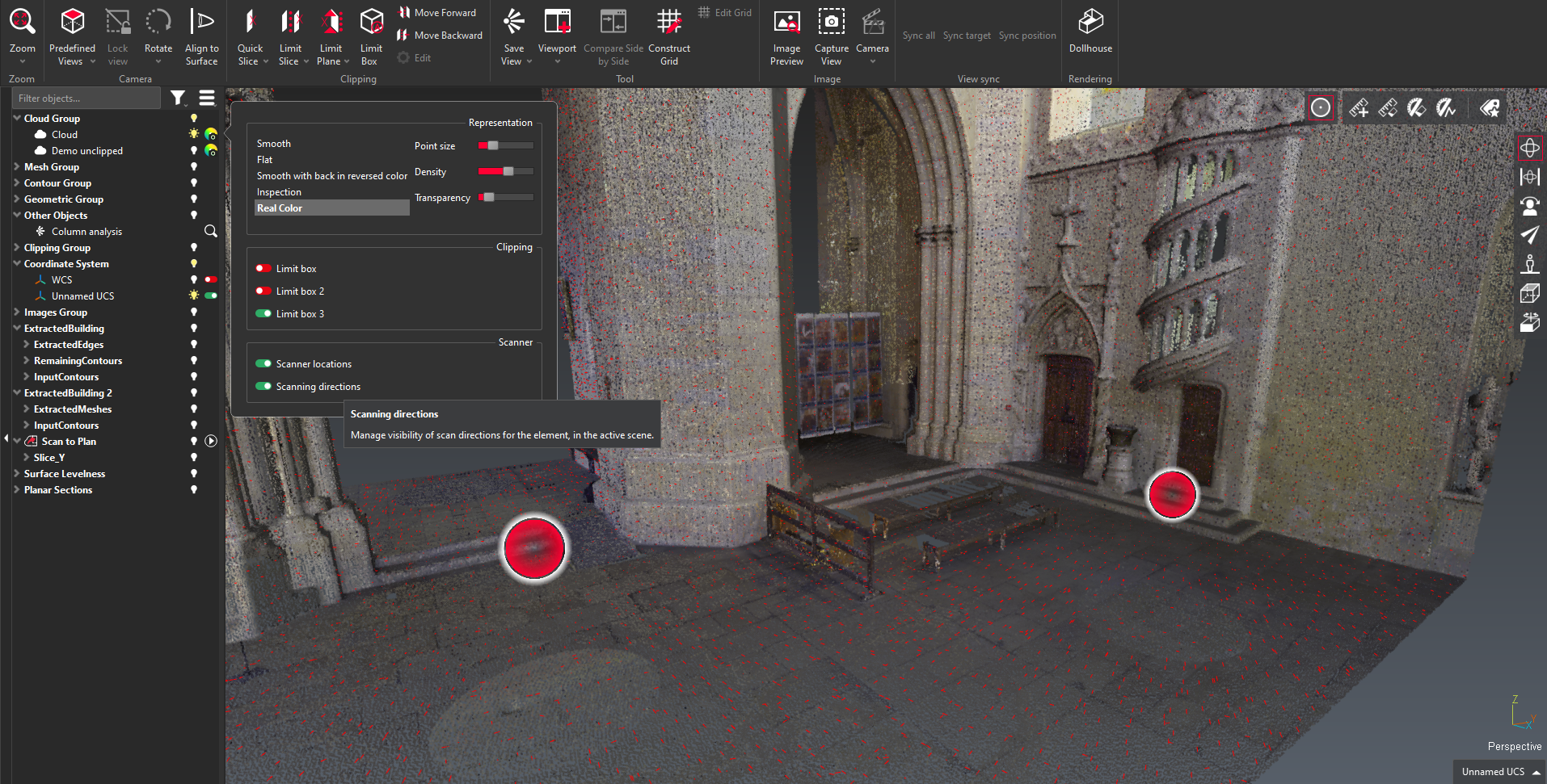
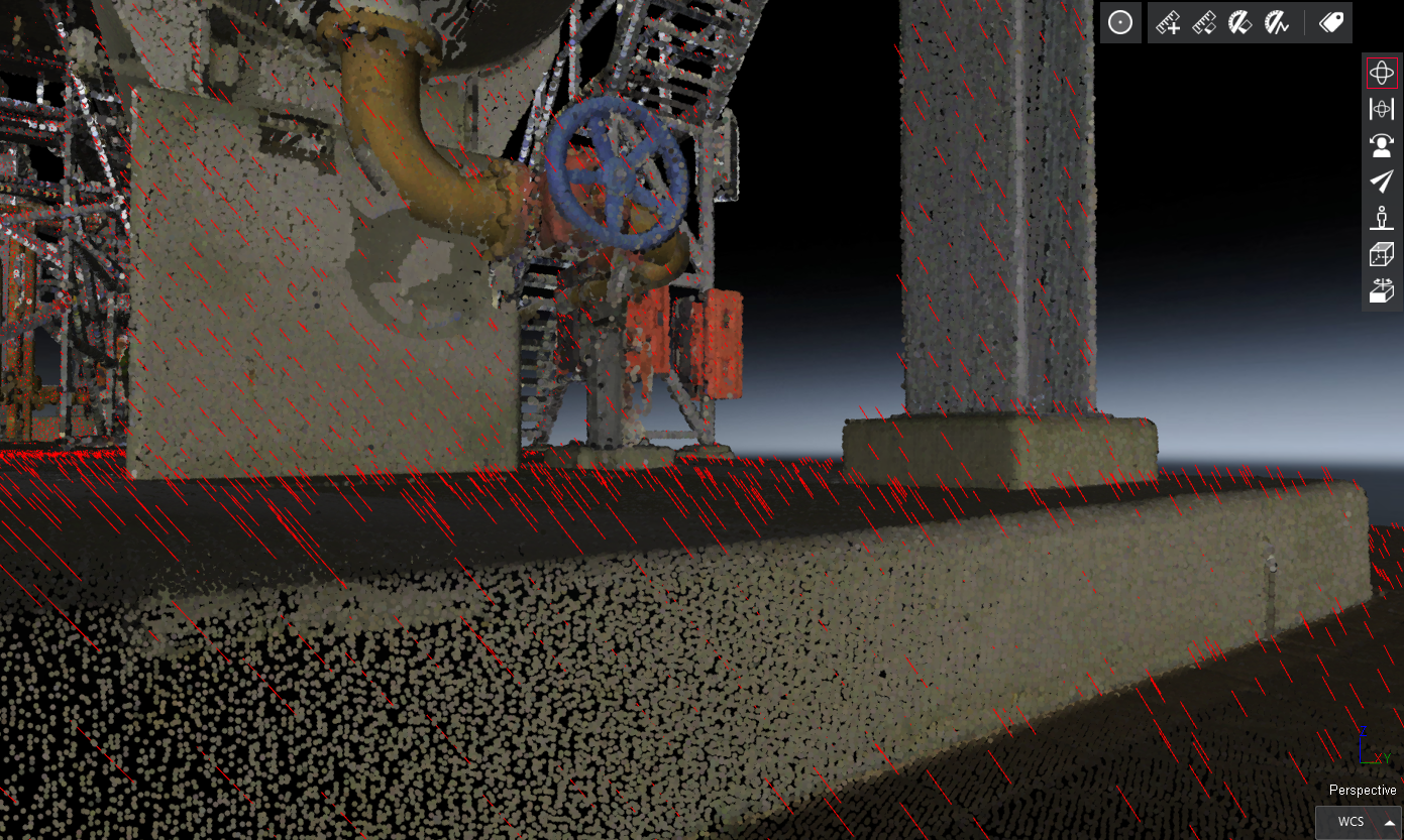
For point clouds that store a scanning direction, a new feature is available from the representation panel of objects and a toggle is exposed to allow users to display or to hide scanning directions.
Static sensors have the capacity to generate the scanning direction information for point clouds and LGSx and e57 are the appropriate formats to import them into Cyclone 3DR.
This feature is useful for advanced meshing workflows when the scanning directions can help to visualize the scanning direction that is used in the 3D meshing process.
Improvements
3D Scene > Background: New SkyBox backgrounds are available which align with Reality Cloud Studio.
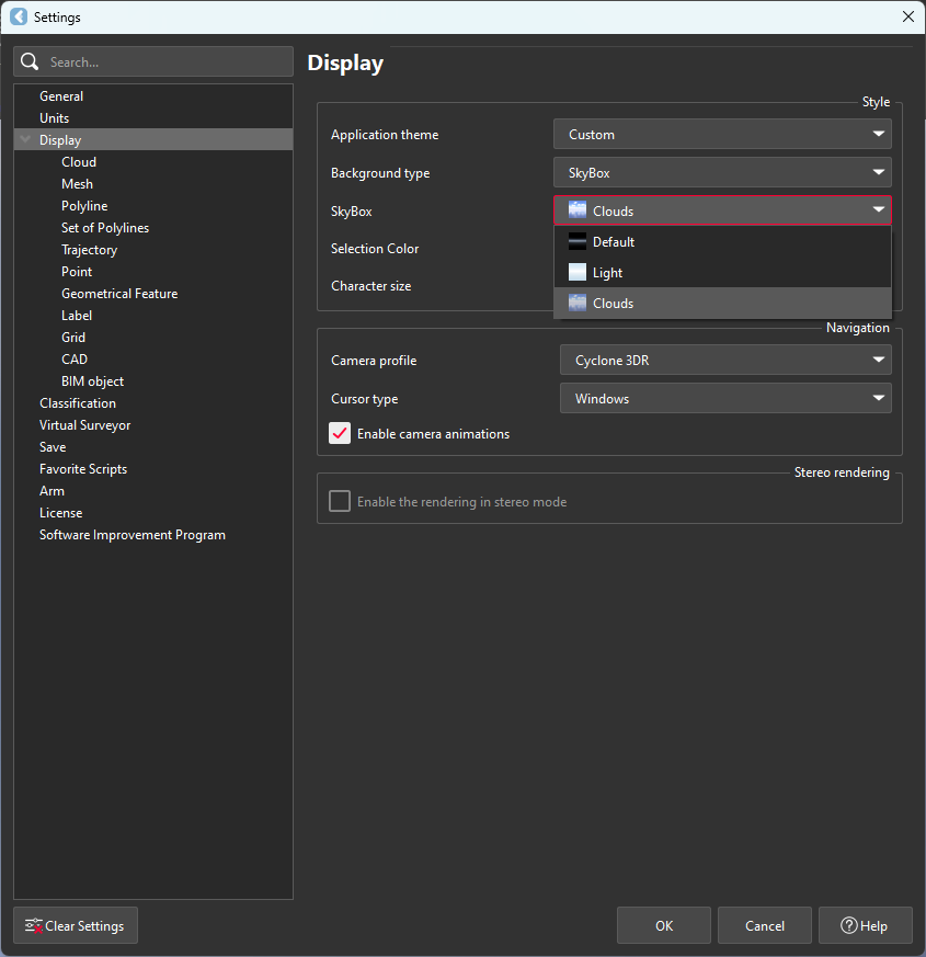
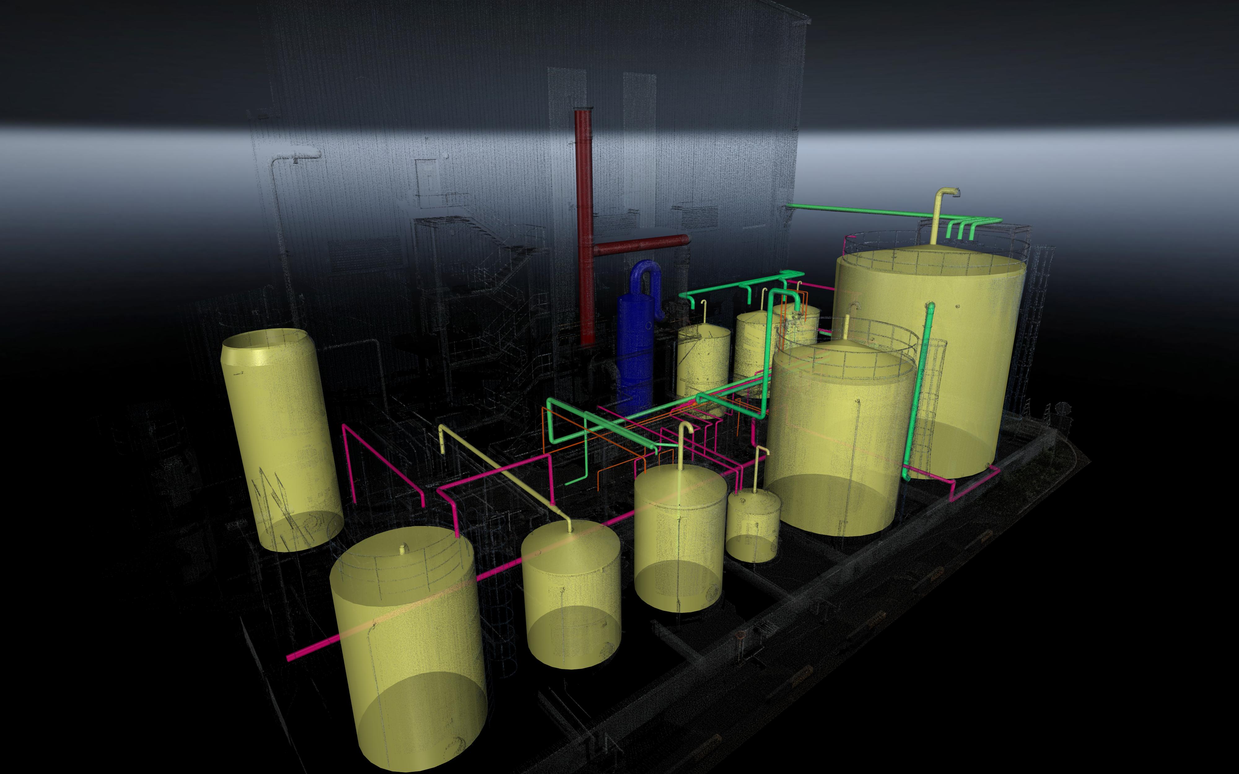 | 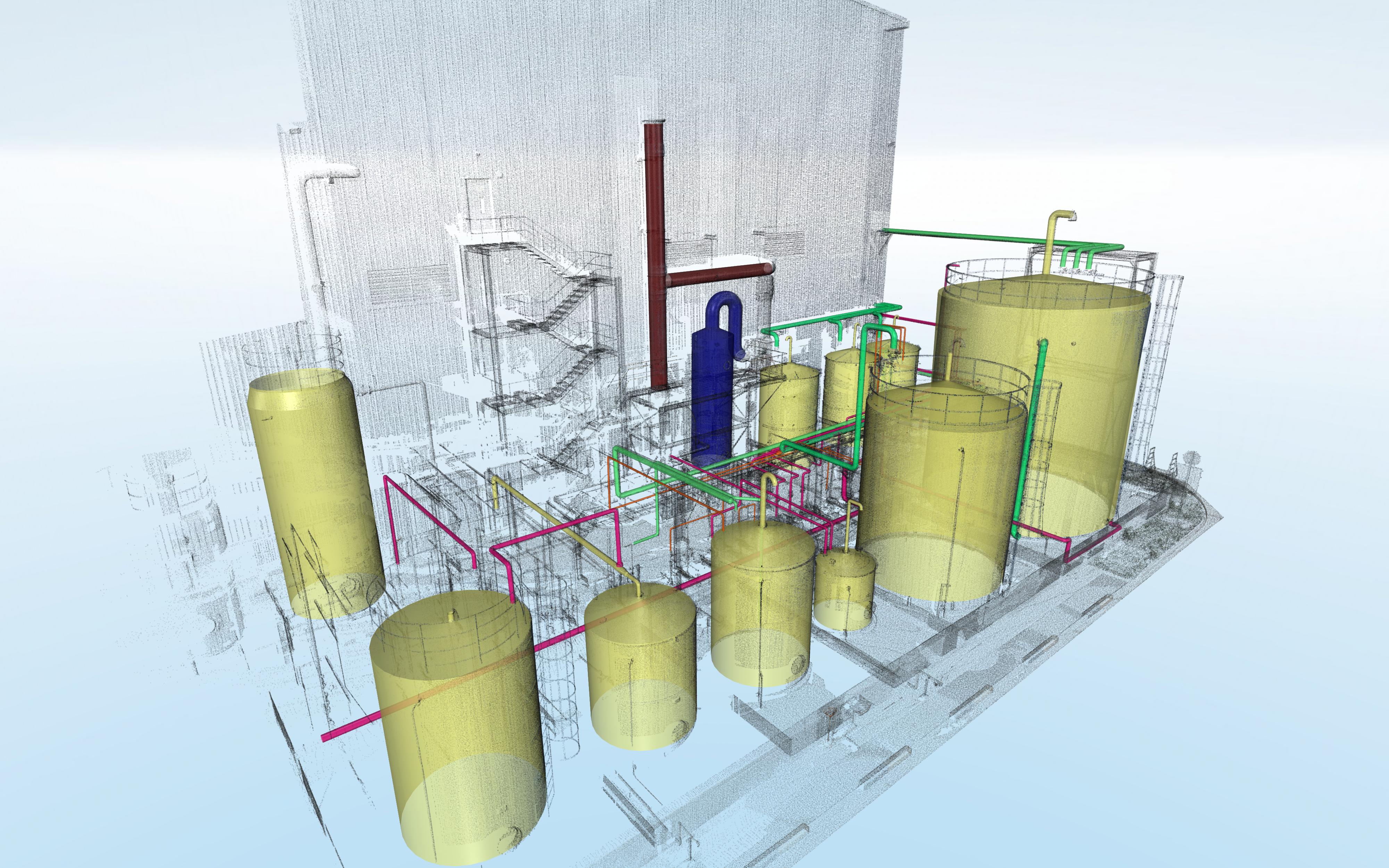 | 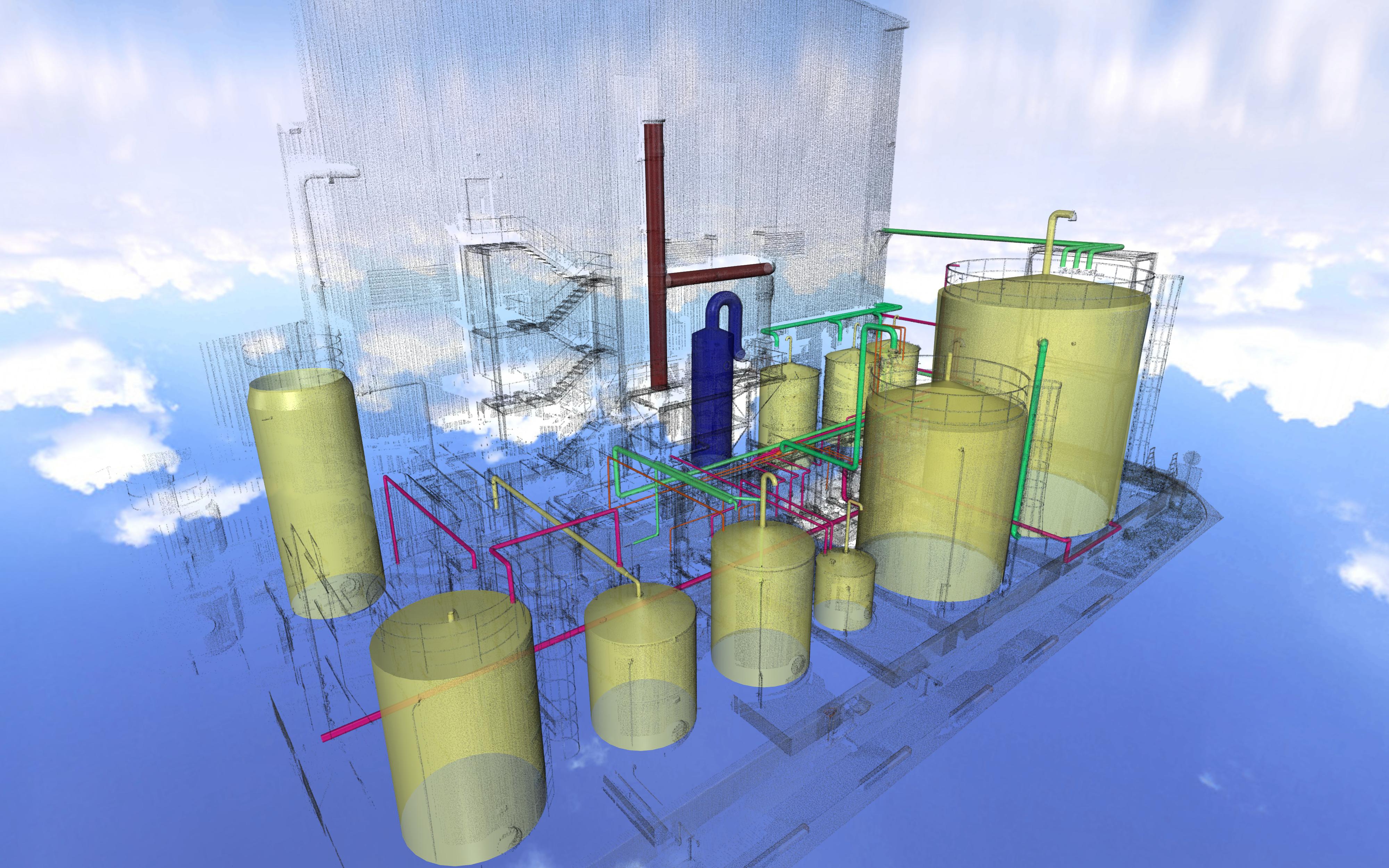 |
3D Scene > Camera: A “smooth scrolling” effect has been introduced while zooming.
3D Scene > Rendering engine improvement: The rendering engine for isolated points, polylines, texts has been improved, which results in significant performance gain in situations when a high number of polylines and in particular inspected polylines are visible in the 3D scene. Some examples are:
Profile 2D or 3D Analysis for very large dataset, which is typical for Mobile Mapping applications
Repetitive inspections like detailed Verticality or Roundness verification in the Tank Inspection workflow.
Application > Icons: Most of the ribbon icons have been modernized with a new design to adhere to a common style and iconography across all reality capture products.
Analysis > Compare/Inspect Section vs Section: A new option is exposed to users to invert the deviation values.
View > Image navigation toolbar: Added a universal visibility toggle to control the image position visibility across the project.
Import > From Cyclone FIELD 360:
Significant improvement of the colors of the points (now based on HDR images).
Undesired black areas on BLK360 scans are now removed.
View > Clipping object editing: When editing clipping objects (slices and boxes), the editing shortcuts have been changed for a better consistency across the application:
ESC: cancel editing
ENTER: validate editing
Script: A new script function is exposed SCloud.HasIntensity() to clarify the usage between inspection and intensity attributes.
Texturing > Adjust Texture: A button was added to select a texture from the 3D Scene.
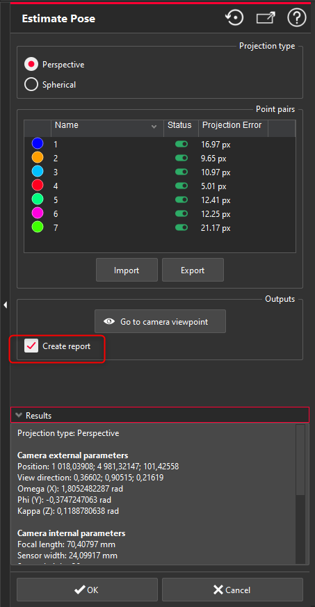
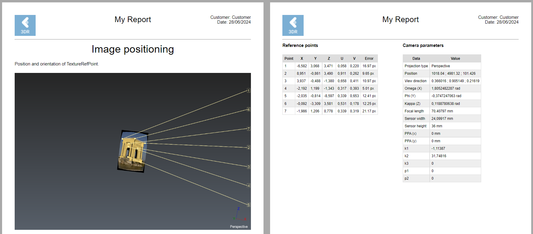
Texturing > Estimate Pose: New capacity to export the results to a report.
Texturing > Smart Texture: The blur effect for blending needs in the transition zones has been significantly removed.
Sensor | With Cyclone 3DR 2024.0 | With Cyclone 3DR 2024.1 |
|---|---|---|
BLK2FLY | 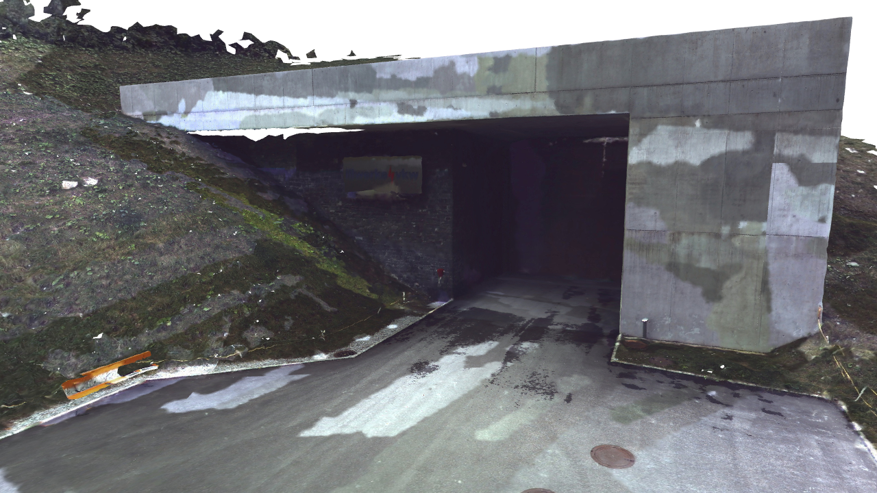 | 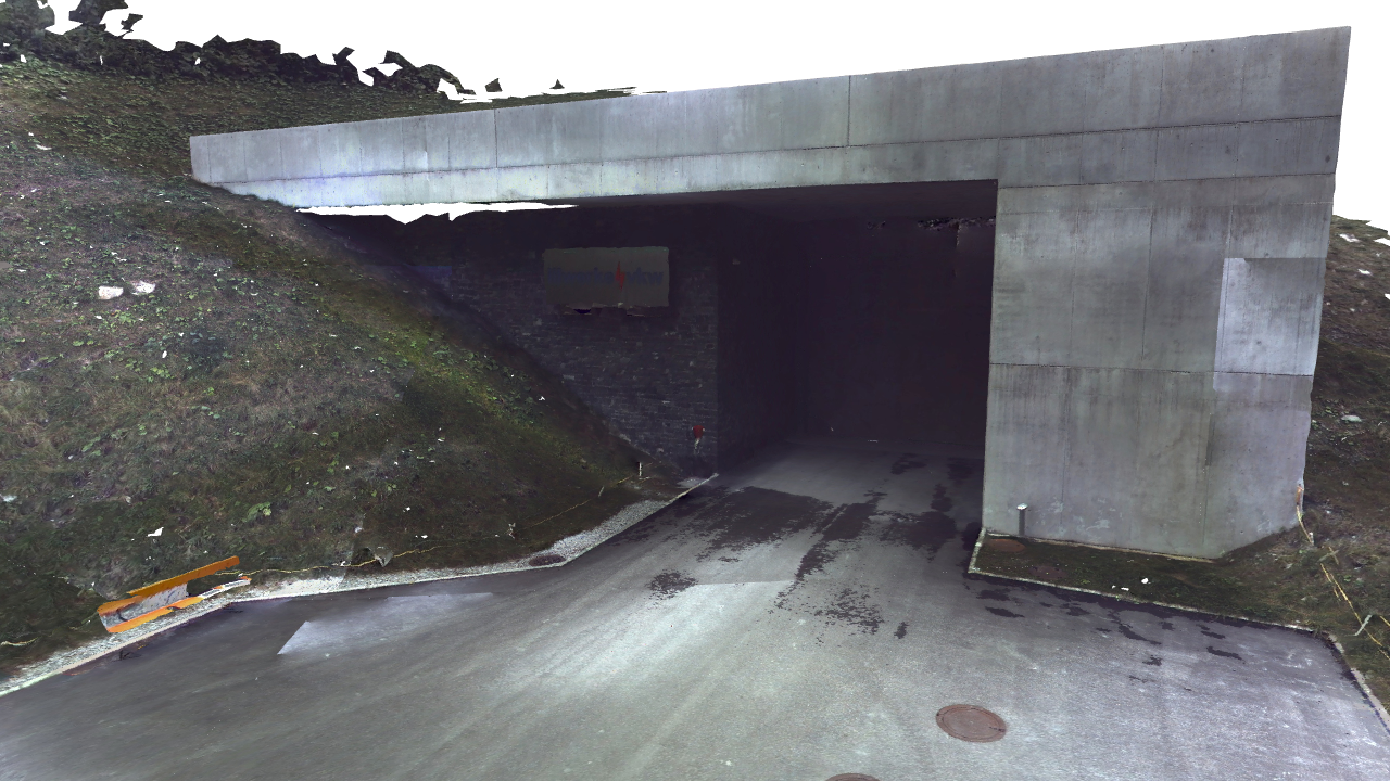 |
BLK2GO PULSE | 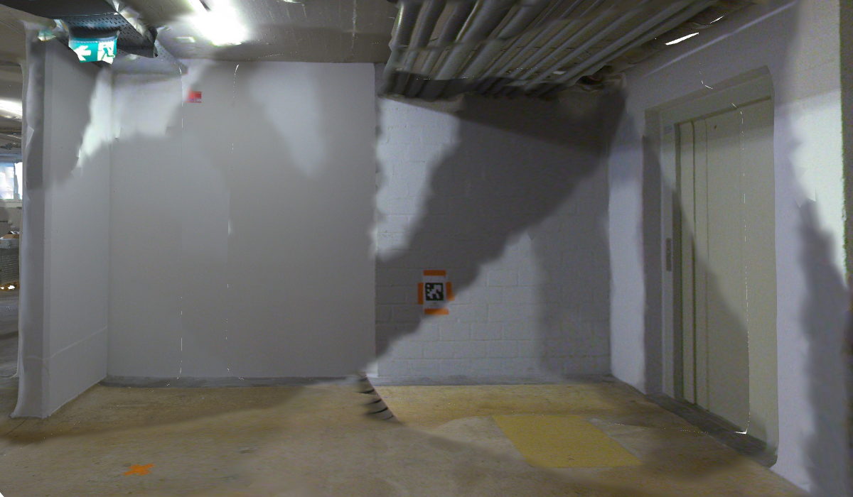 | 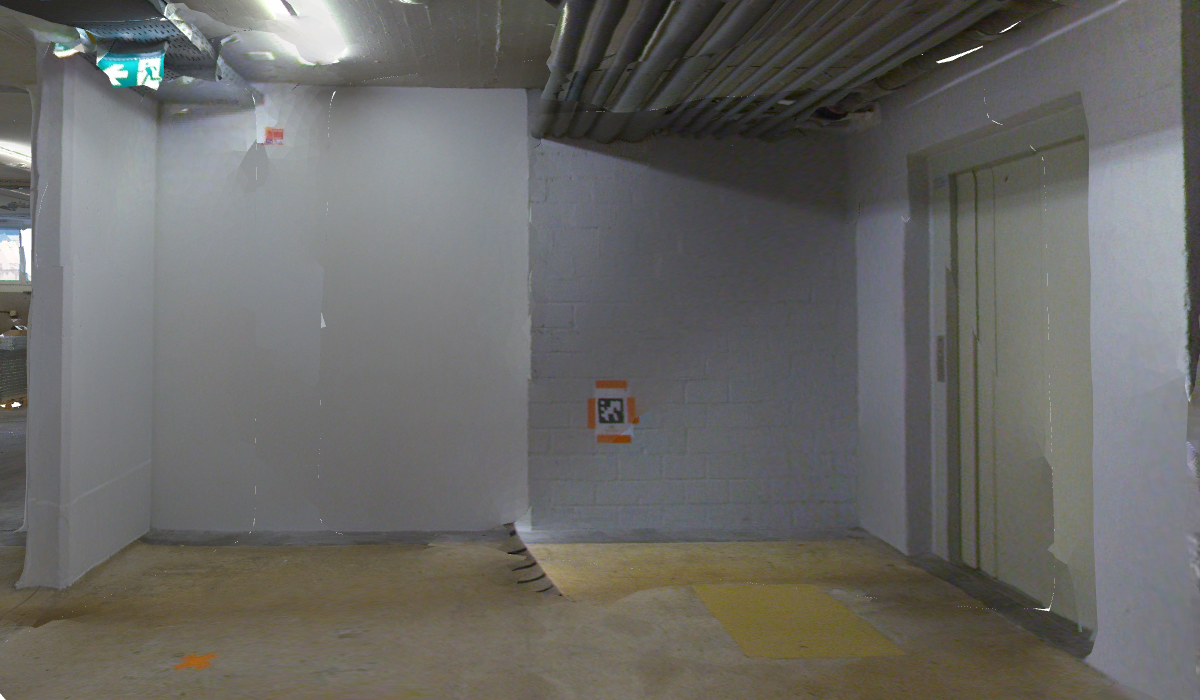 |
BLK360 | 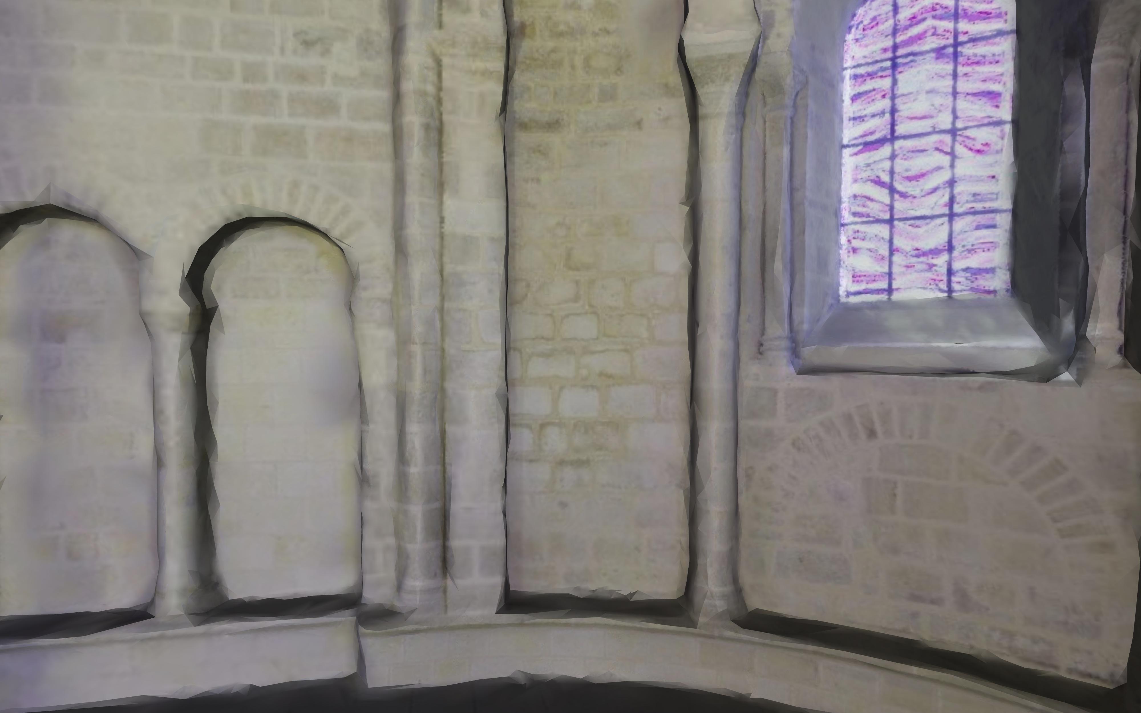 |  |
Bug Fixes
Clean > Join Polylines: Fixed a bug that prevented users from snaping to all extremities.
Report: Fixed a bug that caused labels to be duplicated in high resolution images.
Script > ExportOrthoimage(): Removed a limitation about the dimensions of the exported orthoimages (width and height) that were limited to integer values only. It allows more flexibility for multiple orthoimage creations.
Surface Modeling > Clean / Separate: Fixed a bug that could cause inaccuracy of selection when working with meshes located in large coordinates.
Windows Explorer: Fixed a bug that resulted in the visualization of Cyclone 3DR thumbnails being broken.
Known Issues
The capacity to “Send to Hexagon MinePlan 3D” is broken with Cyclone 3DR 2024.0. The current workaround is to exchange data through CAD files (like DXF format).
The Documentation Center is only available in English.
Some CAD import and export issues might happen. It is recommended to use the Send to CAD feature.
If DXF can be imported with a standard version, DWG requires the AEC or PRO Edition. One workaround is to use the 3DR Send command from AutoCAD to Cyclone 3DR.
Deprecated Features
Leica Geosystems strives to provide support for the widest array of operating systems and file formats possible as is reasonable given current technologies and support from third-party partners.
With each release, we review our list of currently supported formats and operating systems in line with industry trends and announced product terminations.
Leica Geosystems may add or terminate support for a file format during any release. Obsolete operating systems will be supported for six months after their announced termination or the next major software release, whichever comes first. Server products will be supported in alignment with Leica’s Client License Manager (CLM) supported servers to guard users against incompatibility.
Cyclone 3DR 2024.1.0:
CloudWorx > Connect to JetStream Enterprise: JetStream Enterprise begins phased out since 2021, the connection to the product has been removed.
Clean > Explode by Class: replaced by Separate by Attributes
Clean > Scalar Steps: replaced by Separate by Attributes
Clean > Scalar Range: replaced by Separate by Attributes
Generic specifications
Leica Cyclone 3DR 2024.1 compatibility
Cyclone 3DR is compatible with CLM 2.14.0 and higher.
Cyclone 3DR is compatible with LGS/LGSx files.
Cyclone 3DR is compatible with Cyclone ENTERPRISE 2022.0 and higher.
Cyclone 3DR is compatible with Cyclone REGISTER 360 2021.1 and higher.
Cyclone 3DR is compatible with Cyclone IMP databases from Cyclone 6.0 or higher, however improved rendering will only be seen with IMPs from Cyclone 9.3 or higher.
Recommended computer specifications
Regular workflows in desktop application:
CPU: 2 GHz Dual Quad Core i7 or higher (i5 minimum)
RAM for 64-bit OS:
minimum 16 GB
recommended 32GB or more
Graphics Card: NVidia Quadro or GeForce 1 GB (with OpenGL support, versions 4.3 or higher)
Operating system: Microsoft Windows 10 (Build 1809), 11 (64 bits supported)
Hard Disk: 3 GB free disk space
Tablet device for Touch Mode:
Microsoft Surface PRO Core i7 1.5 GHz – 16GB RAM.
Minimum specifications for Auto-classification (in addition to other recommended specifications for the desktop application:
RAM: minimum 32 GB
Graphic Card: NVidia with GPU capabilities
Compute capability: 5.0 or higher
Minimum GPU memory: 4 GB
Hard Disk:10 GB free disk space
CUDA® 11.8 Toolkit (from NVidia). The 11.8 version of CUDA is mandatory for Auto-Classification.
Installation and Licensing Recommendations
Installation update procedure
Launch the Cyclone 3DR EXE and follow the instructions in the Setup Wizard
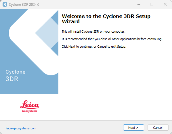
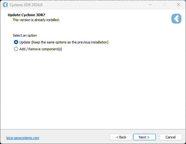
Select the option to update Cyclone 3DR (or repair if you want to change installing options)
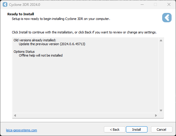
Complete the installation by selecting “Install”.
Licensing setup
Once you have installed Cyclone 3DR, open the Client License Manager for Floating Licenses via Cyclone 3DR (Home/Settings/License) or via the program located here:
Start Menu | All Programs | Leica Geosystems | Client License Manager
Be sure to choose the CLM Floating option (there are two CLM options and the Nodelocked CLM will not activate your license).
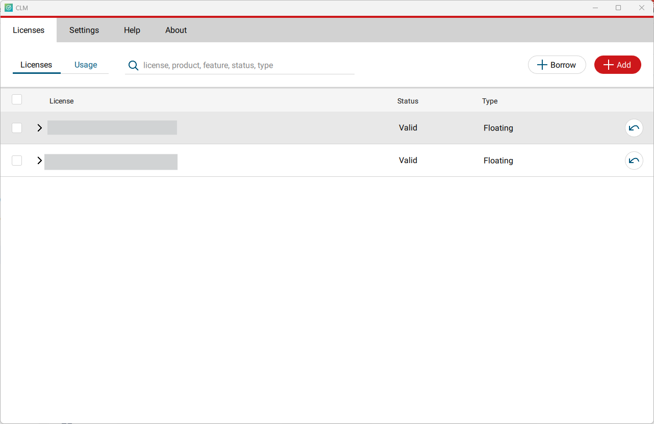
Click Add.
Enter your Entitlement ID (EID) in the field (copy / paste). To enter multiple EIDs separate them with a semicolon ";" and no space.
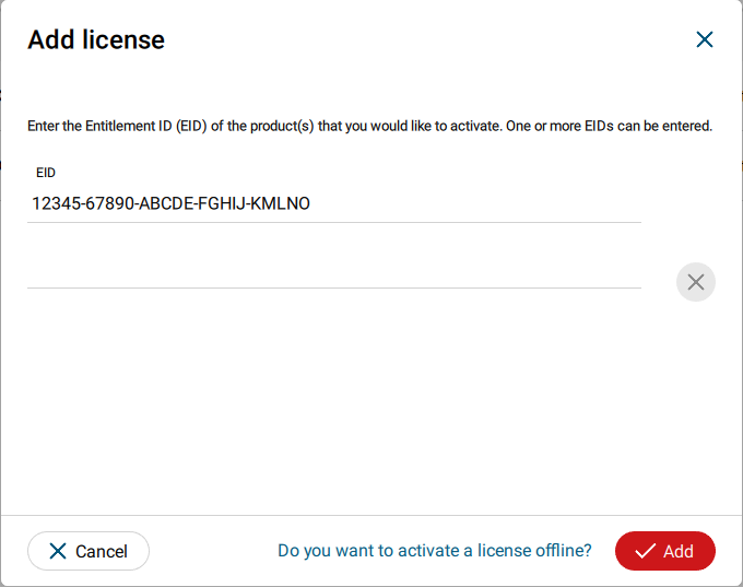
After you have entered your EID, click on the Add button in the bottom right of the page.
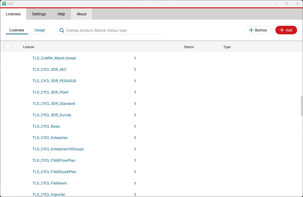
Once your licenses are activated you can close CLM and launch or return to Cyclone 3DR.
Go to Home | Settings and select License.
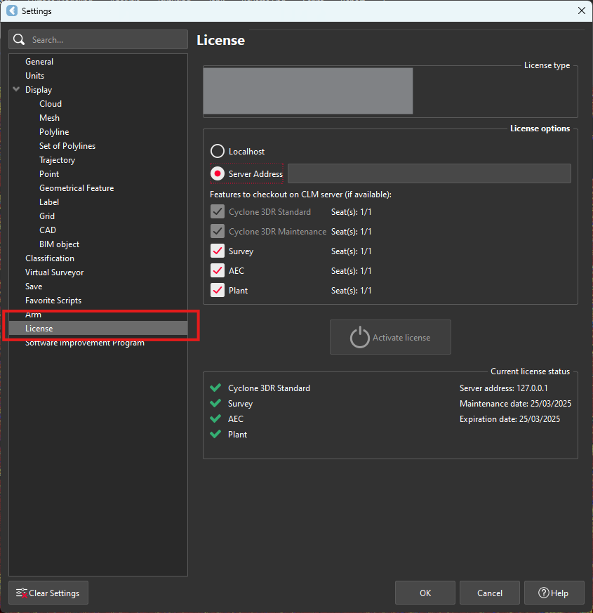
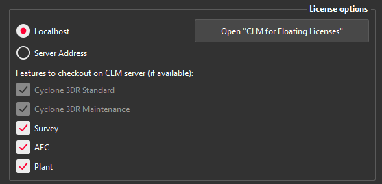
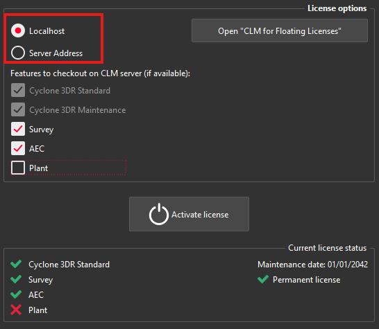
If you have entered the EID inside your local CLM, select Localhost. If the license is on a dedicated server, enter the server’s name in Server Address.
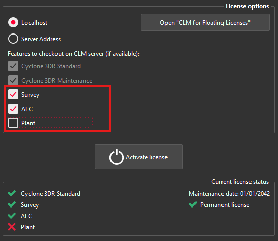
You can select the features you want to check out from CLM. The available options to checkout will correspond to the options you purchased which are contained in your EID.
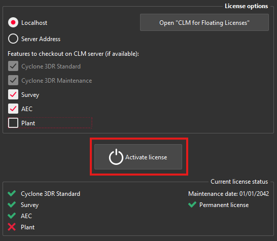
Once the options are selected, click on Activate license.
Licensing
All users with valid CCP or CCP which was valid as of 6 July 2024 for Cyclone 3DR, can run this new version of Cyclone 3DR.
All users with valid CCP or CCP which was valid as of 6 July 2024 for 3DReshaper, can run this new version of Cyclone 3DR with no new license required. Users with 3DReshaper licenses with expired CCP must migrate to Cyclone 3DR in order to continue to access updates and support. Please contact your sales or support personnel for more information.
All users with valid CCP or CCP which was valid as of 6 July 2024 for Cyclone SURVEY, can run this new version of Cyclone 3DR (Standard and Survey Edition features only).
All users with valid CCP or CCP which was valid as of 6 July 2024 for Cyclone MODEL, can run this new version of Cyclone 3DR (Standard and Plant Edition features only).
Interoperability
Import / Export supported file formats
Please reference the Cyclone 3DR Technical Specification for a complete list of supported file types per license.
| Import | Export |
Point Cloud | Files ASCII (*.asc, *.csv, *.xyz, *.yxz…) Leica Geosystems (*.pts, *.ptx) and LGS/LGSX (*.LGS/LGSx) Leica Nova MS50/60 (*.sdb, *.xml) ShapeGrabber (*.3pi) 3DReshaper binary file (*.nsd) AutoDesk DXF (*.dxf) STL (*.stl) Polyworks (*.psl) Leica T-Scan + Steinbichler (*.ac) LIDAR data (*.las; laz) Other ASCII (*.*) Zoller and Fröhlich *(.zfs - *.zfc) PLY points without triangles (*.ply) ESRI ASCII (raster format *.asc) FARO (*.fls - *.fws) POLYWORKS (*.psl) E57 (*.E57 files) LandXML files (*.xml) Riegl (*.RDBX) | ASCII FILES (*.asc, *.csv…) Binary files (*.nsd) Leica Geosystems (*.pts, *.ptx, *LGSx) E57 (*.e57) IGES (*.igs) LAS (*.las) LAZ (*.laz) Autodesk DXF (*.dxf)
|
Mesh | STL format (*.stl) Binary PBI format (*.pbi) DXF 3Dface format (*.dxf) Ascii POLY format (*.poly) OBJ format (*.obj) Ascii Leica format (*.msh) OFF files (*.off) PLY (*.ply) GLB format (*.glb, *gltf) | Ascii and binary STL format (*.stl) Binary PBI format (*.pbi) DXF 3Dface format (*.dxf) Ascii POLY format (*.poly) Vertices only (*.asc) DXF polyline (*.dxf) Ascii Leica format (*.msh) PLY (*.ply) LandXML (*.xml) OBJ format (*.obj) GLB format (*.glb) FBX format (*.fbx) IFC / IFCSite type (*.ifc, *.ifczip) |
Contour / Section | IGES format DXF polyline format Binary MLI format (*.mli) | IGES format DXF polyline format Binary MLI format (*.mli) ASCII formats |
CAD / BIM Models | IGES STEP DWG IFC RVT | IGES STEP DXF IFC (Piping models) |
Project | Cyclone 3DR (*.3dr) DXF - DWG XML Cyclone ModelSpace View (from IMP) | Cyclone 3DR (*.3dr) DXF PDF 3D SKETCHFAB |
Report | CSV BCF | |
Image | BMP JPEG JPG PNG | Ortho-image including georeferencing information as TXT file JPG JPEG BMP PNG TIF (Ortho-image only) |
Trajectory (mobile scanner) | Leica Geosystems (*LGSx) | Leica Geosystems (*LGSx) |
Send To / Send From
Cyclone 3DR provides “SendTo” features as well to import and export certain kinds of data with third-party products. More information is available in Cyclone 3DR documentation center (from the software help menu).
| Send From | Send To |
Point Cloud | - | - |
Mesh / Surfaces | Autodesk AutoCAD Hexagon MinePlan 3D Hexagon BricsCAD | Autodesk AutoCAD Hexagon MinePlan 3D Hexagon BricsCAD |
Contour / Section / Points | Autodesk AutoCAD Hexagon MinePlan 3D Hexagon BricsCAD | Autodesk AutoCAD Hexagon MinePlan 3D Hexagon BricsCAD |
CAD Model | Autodesk AutoCAD Hexagon BricsCAD | - |
Image | - | Autodesk AutoCAD (ortho-image) Hexagon BricsCAD |
The following commands in Cyclone 3DR include a direct “Send to” capacity that provides the possibility to export the outputs in different layers in the CAD 3rd party software product:
Menu | Feature | Comment |
Extract | Contour Lines | 1 layer for standard contour lines and values. 1 layer for major contour lines and values. |
Extract | Scan to Plan | 1 layer per slice (floorplans or sections) |
Extract | Virtual Surveyor | 1 layer per layer created in 3DR Virtual Surveyor project. |
Extract | Scan to Pipe | 1 layer per pipe trace |
Analysis | Gridded Inspection Surface Analysis with a Grid | Points and values on grid can be directly sent to CAD SW product. Sent to active layer. |
Texturing | Extract Orthoimage | Sent to active layer. |
Analysis | Profile Extraction Profile 3D Inspection Profile 2D Inspection | 1 layer for 2D Grids 1 layer for inspection objects 1 layer per section 1 layer per axis points 1 layer per axis point quotations. |
Tank | 2D Preview / Export |
Compatibility with native JetStream point clouds
The following commands can use native JetStream point clouds (LGS/LGSX files or connection to Cyclone CORE, Cyclone REGISTER 360, Cyclone ENTERPRISE) as inputs. In other words, it is not required to proceed a CloudWorx > Convert project step prior to execution of the listed features.
Menu | Feature | Comment |
Extract | Virtual Surveyor | No selection is required for this feature. Thus, it can be used for any kind of object in a 3DR project. |
Extract | Scan to Plan | |
Surface Modeling | Scan to Mesh | A clipping box as input is recommended to define an area of interest. |
Analysis | Stockpile | |
Analysis | FF/FL Analysis | A maximum number of points is exposed in the first step of the workflow. It is recommanded to keep a high value to execute an accurate analysis on a dense point cloud. |
Analysis | Visual Notes | No selection is required for this feature. Thus, it can be used for any kind of object in a 3DR project. |
The functionalities of the menus View, CloudWorx and Script can obviously be used for JetStream point clouds.
With the capacity to stream images from LGSx files since the 2024.1.0 version of Cyclone 3DR, it is not required to convert the project to visualize the camera images anymore. However, it remains necessary to convert them when the images are used for specific features:
Menu | Feature | Comment |
Texture | Smart Texture Standard Texture Edit Mask | It is mandatory to convert the images from the LGSx when a texturing workflow with images is expected by the user. |
Image object usage | Group / Ungroup | In the treeview, only the converted images from the LGSx file can be grouped and ungrouped. |
Connect to Cyclone FIELD 360
The connection from Cyclone FIELD360 to Cyclone 3DR (2024.0 later versions) projects is limited to TLS sensors:
P-Series
RTC360
BLK360, BLK360 G1
Export BCF tickets
The following commands embed the capacity to export BCF (BIM Collaboration Format) files that contain information from IFC model for an open-BIM experience with other software and BIM solutions.
Cyclone 3DR 2024.1 supports BCF 2.1 format (export).
Menu | Feature | Comment |
Analysis | Inspection Notes | Input: Inspected BIM Model Feature to report issues from an inspection and that gives the ability to create manual notes that contains screenshots, images from disk, labels and deviation values (attached CSV), clipping object information and coordinates and orientation of viewpoint; but also, a user-defined title, an assignment (email address), a comment and a priority. |
Analysis | Visual Notes | Input: BIM Model Feature to report comments and notes based on visual analysis of a BIM design model and the captured reality. The feature gives the ability to create manual notes that contains screenshots, images from disk, distance measurements, clipping object information and coordinates and orientation of viewpoint; but also, a user-defined title, an assignment (email address), a comment and a priority. |
Analysis | Clash | Input: A point cloud and a BIM Model Feature to report clashes that contain screenshot, clash status (clash, no clash or undefined) and a comment. All tickets refer to the same assignment (email address). |
Analysis | Progress Monitoring | Input: A point cloud and a BIM Model Feature to report the progress monitoring analysis. Default export contains a summary (progress distribution between installed, in progress, not installed and no data). Ability to customize the export and to create additional single tickets per analyzed element depending on their status (installed, not installed, in progress). All tickets refer to the same assignment (email address). |
Touch Mode | BIM Inspection | Input: A point cloud and a BIM Model The “Touch Mode” BIM Inspection workflow also offers a way to create BCF issues. The contents are similar to the notes that are exported from “Inspection notes”, which is the desktop equivalent of BIM Inspection. |
Classification experience
Exchange formats for classification
Classification of point clouds is saved and supported for the following exchange possibilities:
Import and Export: LGSx, E57, LAS, LAZ
Stream and Convert: from Reality Cloud Studio, powered by HxDR
Models
Within the 2024.1 version of Cyclone 3DR, the following classification models are exposed in the Auto-Classification feature.
Name | Application | Used scanners for training | Other recommendations | Features using class information |
Indoor Generic | Indoor – All | All | Relevant for Scan to Model workflows. | |
Indoor Construction Site | Indoor – All | All | Relevant for “Scan to Verify” workflows for as-built verification for example. | Progress Monitoring |
Outdoor for TLS | Outdoor – All | TLS | Generic classification that can be used with other sensor types. | |
Heavy Construction UAV | Outdoor - Heavy Construction | UAV Sensors | Recommended for Heavy Construction environment only. Can be used with other sensor types. | Relevant to execute before Virtual Surveyor, DTM |
Mobile BLK Filter People | All | BLK2GO and BLKARC | Recommended with BLK2GO and BLKARC only. Clean moving people and objects. | |
Road for MMS | Roads | TRK series | Recommended with all MMS sensors and useful with TLS scanners like RTC360 and BLK360 to do extraction. | Relevant to execute before Virtual Surveyor, DTM |
Plant | Plant facilities, MEP environment | All | Recommended with static scanners | Relevant to execute before Scan to Pipe |
