This guide details the workflow of using the Wall Fitter tool in CloudWorx for Revit.
Practice Data
Initial Procedures
Importing Project Data
-
Import a dataset using an appropriate import option.
In this workflow, a dataset is saved as the LGSx file, which is then imported as follows:
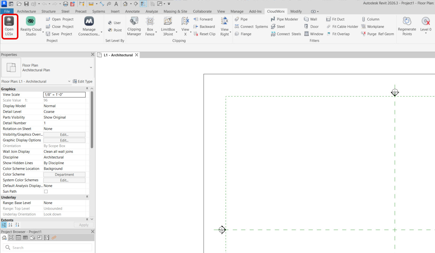
1.1. In the Project panel, click Open LGSx File and browse to the required file.
Adjusting Level Extents
-
To ensure accurate wall heights when the workflow is completed, make sure to position the floor and ceiling levels so they exactly match the corresponding elevations in the imported point cloud.
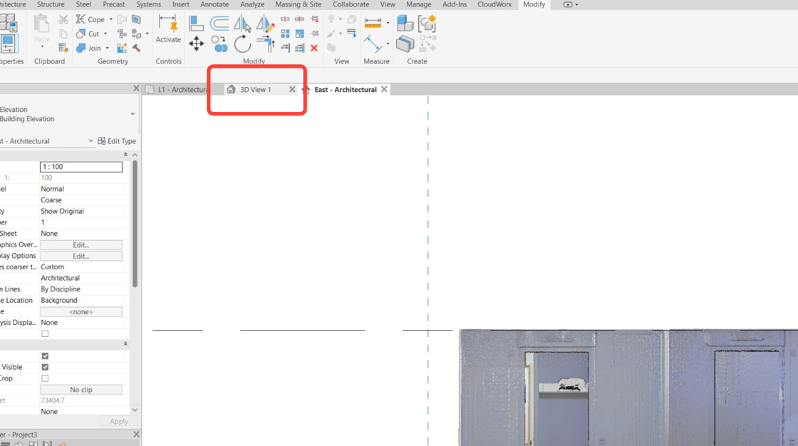
2.1. In Revit’s Project Browser, navigate to Elevations and select the desired elevation view. In this case, it’s East.
.png?cb=3436f48500ce881b4f460f6da6d855d6)
As the default elevations don't match the point cloud, the levels should be moved in elevations.
2.2. Click Level 1 and drag it down to align with the floor.

2.3. Click Level 2 and drag it down to align with the ceiling.

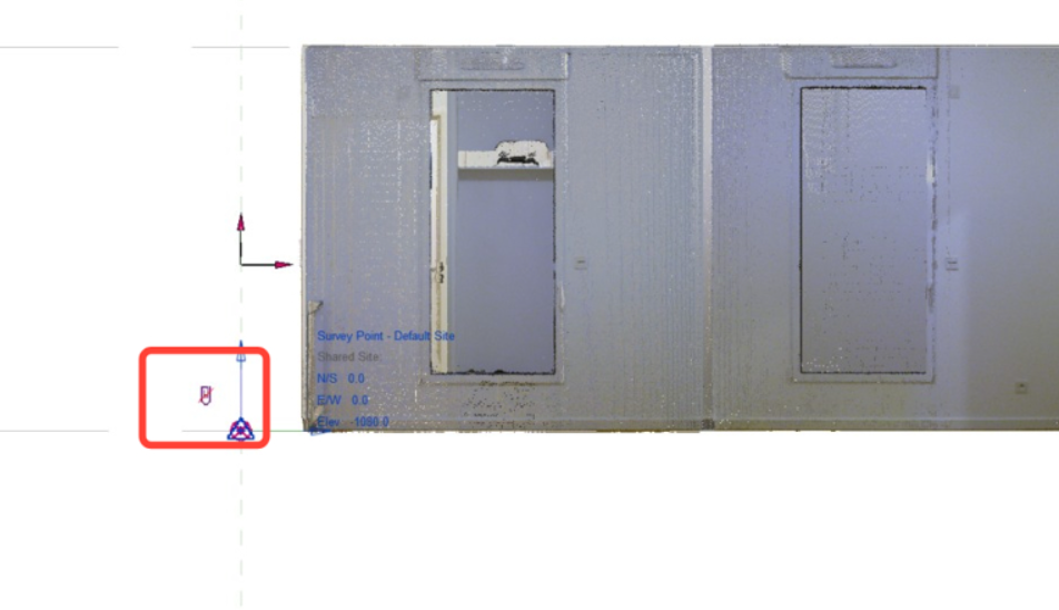
Locating Project Base Point and Survey Point
-
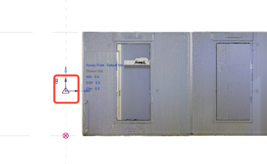
In the View Control Bar at the bottom of the Revit window, click the Reveal Hidden Elements icon to unhide the project base point and survey point.
-
Set both the project base point and the survey point to the L1 line so that the elevation at L1 is 0. This approach ensures consistent distance measurements and precise alignment of objects.

-
Don't forget to unclip the survey point before moving it and clip it again once it has been relocated.
-
Click Close Reveal Hidden Elements.

-
Switch back to the 3D view.
Setting Fence
-
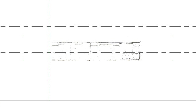
To temporarily hide unnecessary points, navigate to the CloudWorx tab and click Polygonal Fence in the Clipping panel.

-
After activating the tool, outline the area as shown in the image on the left. The result will appear as shown in the image on the right.


-
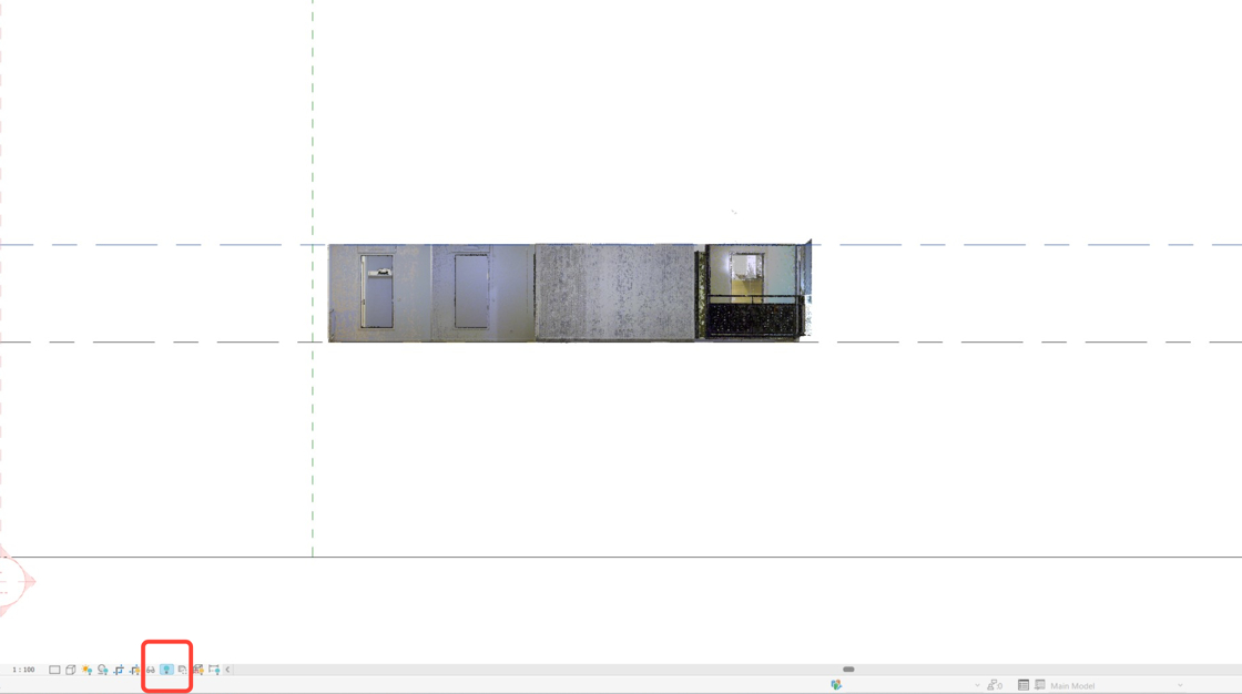
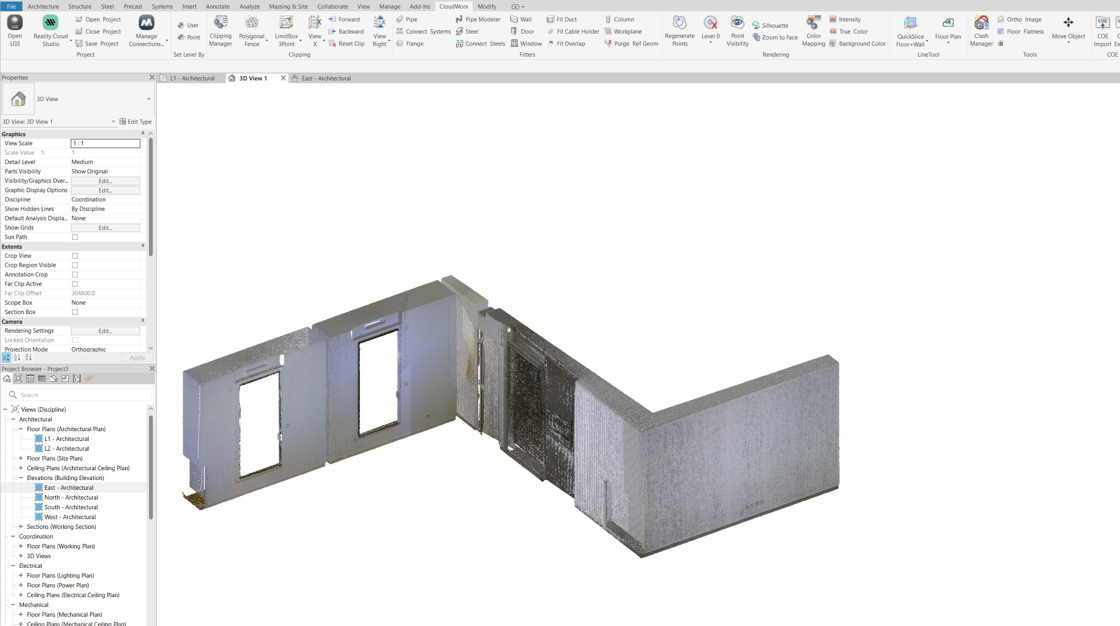
Rotate the cloud to an oblique angle.
Wall Extraction
Understanding Wall Structure
-
To ensure accurate wall placement, familiarise yourself with how wall structures are created in Revit.
Wall types can be built from several layers covering finish, structure, membranes, air space, etc. See the diagram below.

CloudWorx for Revit identifies walls by interpolating a planar surface from a point cloud. The plane cannot be viewed; it remains hidden throughout the selection process. The tool then places a user-defined layer of the selected wall type parallel and coincident with the interpolated plane (IP).
Thus, when the Wall Fitter tool is activated, it is important to clearly distinguish between the following settings:
-
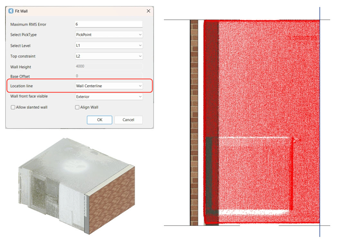
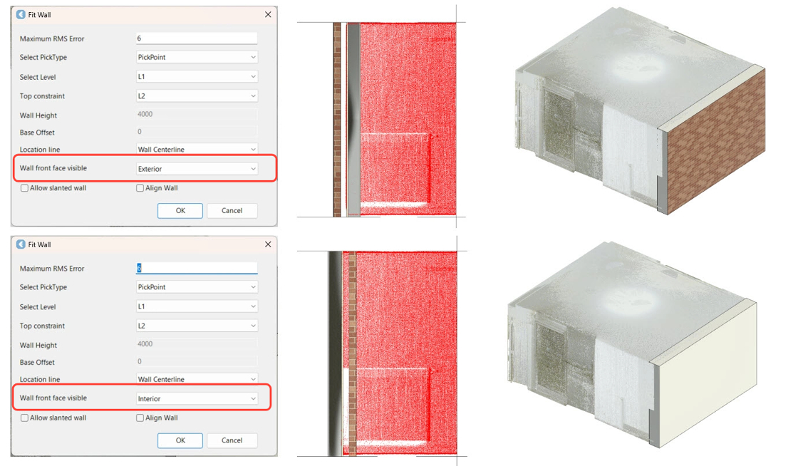
When Wall Centerline is selected in the Location line field, the centre of all layers will be placed on the IP, regardless of the structure.
-
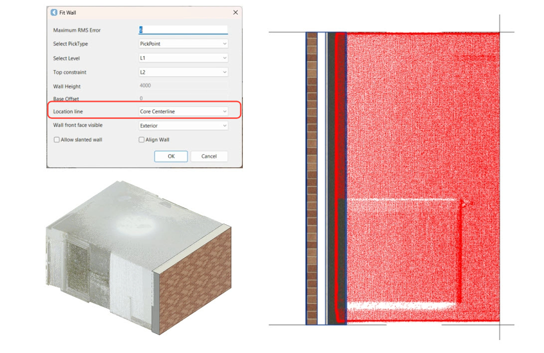
Selecting Core Centerline in the Location line field places the centre of the core boundary layers on the IP, which roughly aligns with Layer 6 in the Wall Layers diagram.
-
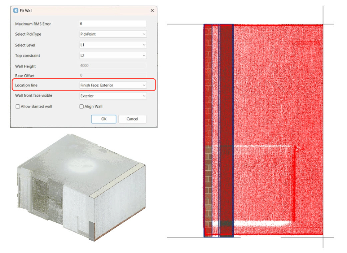
Selecting Finish Face: Exterior in the Location line field places the external face of the wall on the IP, which roughly aligns with Layer 1 in the Wall Layers diagram.
-
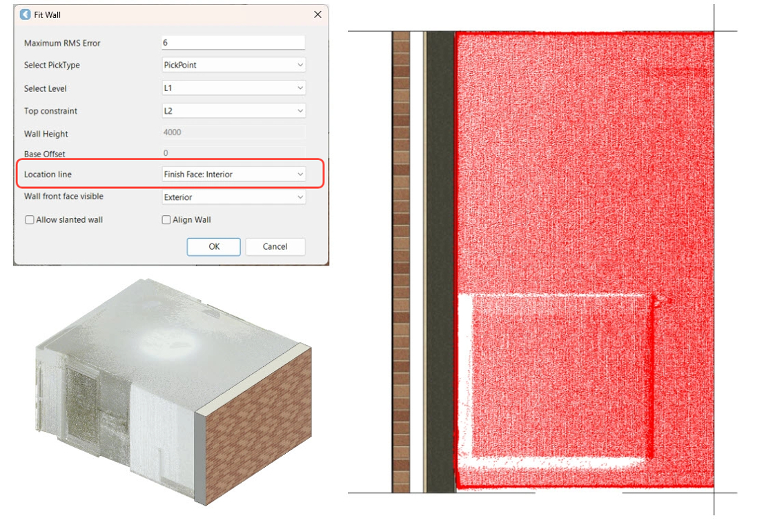
Selecting Finish Face: Interior in the Location line field places the internal face of the wall on the IP, which roughly aligns with Layer 9 in the Wall Layers diagram.
-
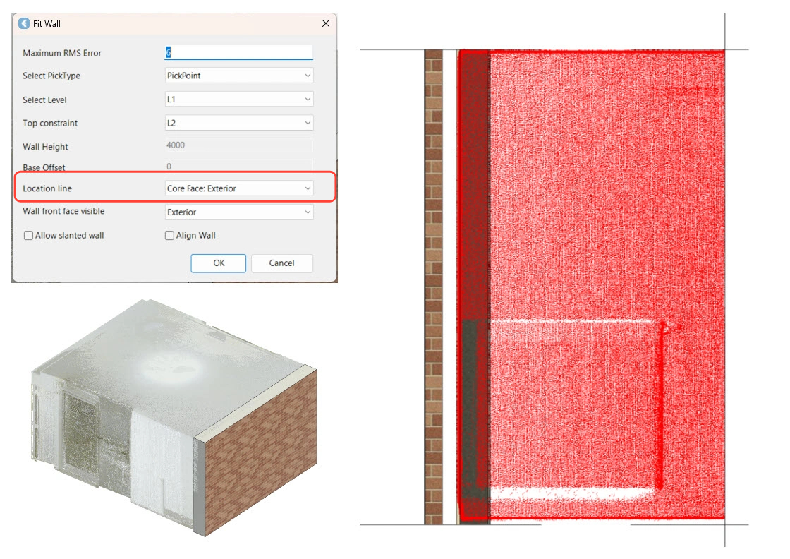
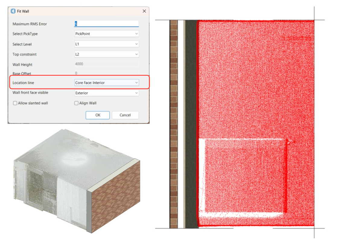
Selecting Core Face: Exterior in the Location line field places the external face of the wall on the IP, which roughly aligns with Layer 5 in the Wall Layers diagram.
-
Selecting Core Face: Interior in the Location line field places the external face of the wall on the IP, which roughly aligns with Layer 7 in the Wall Layers diagram.
-
The Wall front face visible setting orients the wall based on the view of the user. For example, select Exterior when fitting walls from the outside view, and Interior when fitting walls from the inside view.
Extracting Walls
-
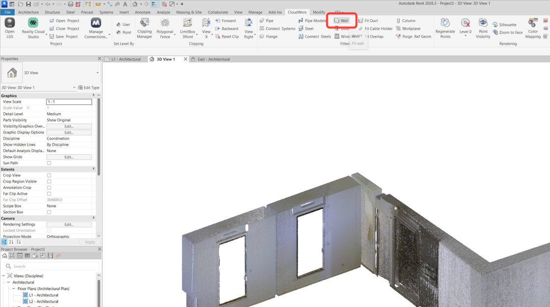
In the Fitters panel, click Wall to activate the Wall Fitter tool.
-
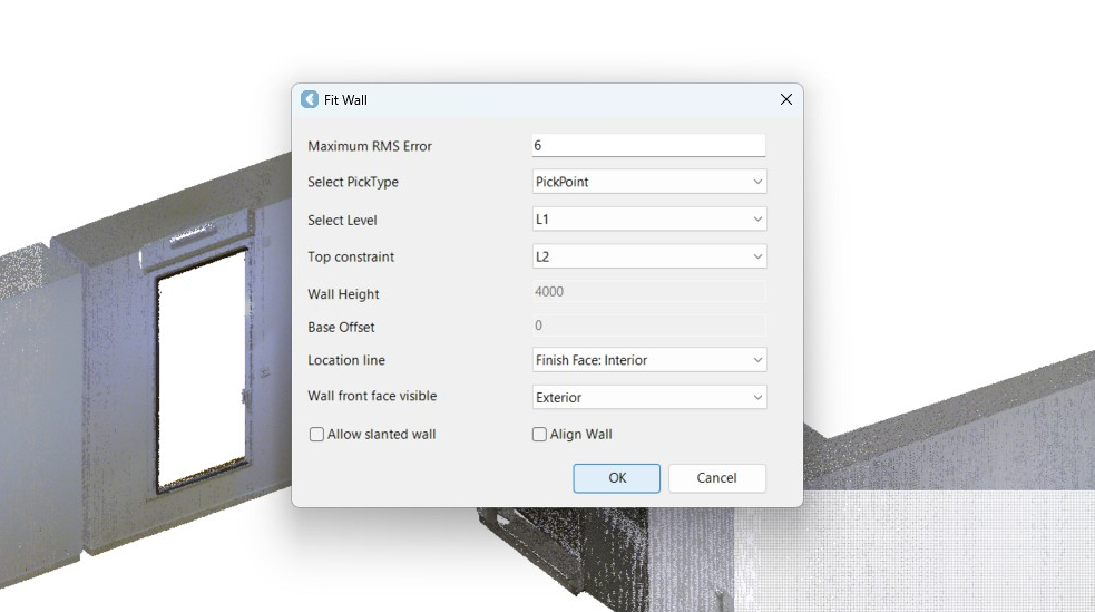
For this example, use the following settings:
-
Set PickType to PickPoint.
-
Set Top constraint to L2.
-
Set Location line to Finish Face: Interior.
-
Set Wall front face visible to Exterior.
-
Click OK.
-
-
Click the first wall face.

-
For this example, use the default wall type: brick on metal stud. Click OK.
Note: By selecting the Create new type check box, you can add a wall with a custom thickness and assign it a new name. This option does not create a new wall; it only allows you to create a new wall type with a specified thickness based on families already loaded into the project.

-
Click the next wall face and then click OK to save it.


-
Continue extracting additional wall faces.


-
Press Esc to exit the tool.
Adjusting Extracted Walls
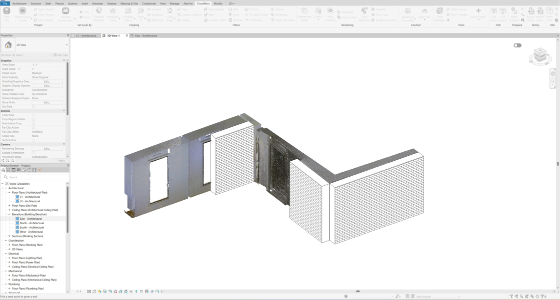
Now there are three walls extracted. If the environment makes it difficult to identify a complete wall, you can easily adjust it in Revit.
-
Double-click and open up the L1 floor plan.

-
Join the walls.
If wall joins are enabled in Revit, walls can be dragged or extended to connect with one another.

-
Adjust the wall length by dragging it.

-
Go back to the 3D view and check the result. Three walls have been extracted, allowing for the subsequent placement of windows and doors.
